2
Instruction Leaflet IL
66A7638H03
Effective December 2010
Instructions for DNP MINT Translator Module
Installation and Use
EATON CORPORATION www.eaton.com
I.L. 66A7638H03
Effective September 2007
2
5.6
INCOM 100
Ω
Termination DIP Switch (SW1) ......................................................................6
5.7
DNP RS-485 Baud Rate DIP Switch (SW2)............................................................................6
5.8
DNP Diagnostics Enable (Configuration Mode) Switch (SW2).................................................6
5.9
DNP/RS-485 121
Ω
Termination DIP Switch (SW3)...............................................................6
6.0
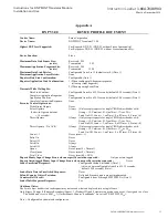
DNP V3.00 DEVICE PROFILE................................................................................................6
7.0
DNP MINT CONFIGURATION USING AUTO LEARN ..........................................................7
8.0
DNP MINT CONFIGURATION USING DNP COMMUNICATIONS.......................................8
8.1
Configuration With Pre-Defined Tables..................................................................................8
8.2
Configuration Of Summary Table Settings............................................................................10
8.2.1
DNP Master Station Address.........................................................................................10
8.2.2
DNP Address...............................................................................................................11
8.2.3
Configuration Tag.........................................................................................................11
8.2.4
DNP Transfer Protocol..................................................................................................12
8.2.5
DNP Network Idle Time To Initiate Unsolicited Transmission.........................................12
8.2.6
DNP Network Unsolicited Retry Random Time Increment Mask.....................................12
8.2.7
DNP Data Link Confirmation Wait Timeout...................................................................12
8.2.8
DNP Application Confirmation Wait Timeout................................................................13
8.2.9
INCOM Scan Level Settings..........................................................................................13
8.2.10 DNP Object Variation Default Settings ..........................................................................13
8.2.11 INCOM Address Settings..............................................................................................13
8.2.12 INCOM Scan List Index Settings...................................................................................14
8.3
Configuration With File Transfers........................................................................................15
List of Figures
Figure 1: The DNP MINT Module ......................................................................................................1
Figure 2: DNP MINT in a Communications Network...........................................................................4
Figure 3: Connections ........................................................................................................................5
Figure 4: Switches.............................................................................................................................5
List of Tables
Table 1: Power Connector Pin Outs ....................................................................................................5
Table 2: INCOM Connector Pin Outs..................................................................................................5
Table 3: DNP RS485 Connector Pin Outs............................................................................................5
Table 4: RS-485 Baud Rate Switches..................................................................................................6
Table 5: RS-485 Diagnostics Enable (Configuration Mode) Switch.......................................................6
Table 6: Auto Learn INCOM Devices.................................................................................................7
Table 7: Pre-Configured Counter Assignments ....................................................................................9
Table 8: DNP MINT Summary Table Definitions ..............................................................................11
Table 9: Device Summary Table Definitions......................................................................................14
Table 10: Device Assignments for Pre-Defined Configuration Tags ....................................................19
Table 11: Primary Status Code Definitions ........................................................................................69
Table 12: Secondary Status Code Definitions.....................................................................................69
Table 13: Cause-of-Status Code Definitions ......................................................................................70
Table 14: MPCV Relay Primary / Secondary / Cause Decoding ..........................................................73
Table 15: MPCV Relay Product ID Decoding....................................................................................74


