background image

Page 4 

.

Effective.June.2007

RS-485 PONI

66A2070 Rev. B

Signal Polarity

The data is considered a binary  when the voltage level 

of the “A” signal is less than the voltage level of the “B” 

channel. A binary  is considered a Mark or OFF, where as 

a.binary.0.is.a.Space.or.ON .

Cabling

The recommended cable for maximum performance of 

the RS-485 network has a twisted-pair, 22-AWG stranded 

7 x 30 conductors with PVC insulation under aluminum foil 

polyester tape, a single 24-AWG stranded 7 x 32 conductor 

with PVC insulation and aluminum foil polyester Tape, plus 

an all-over braided shield (Belden 306A). Cables with 

similar shielding and smaller wire sizes (24 AWG) can be 

used for easier wiring. The cable characteristic impedance 

should be 20 ohms.

RS-485 Bus Termination

Assuming the characteristic impedance of the cable is 

20 ohms, each segment of the RS-485 network should 

be terminated with an end-of-line terminating resistor. A 

resistor value of 20 ohm should be used at the Master end 

of the network as well at the end of the line.

RS-485

PONI

RS-485

PONI

RS-485

PONI

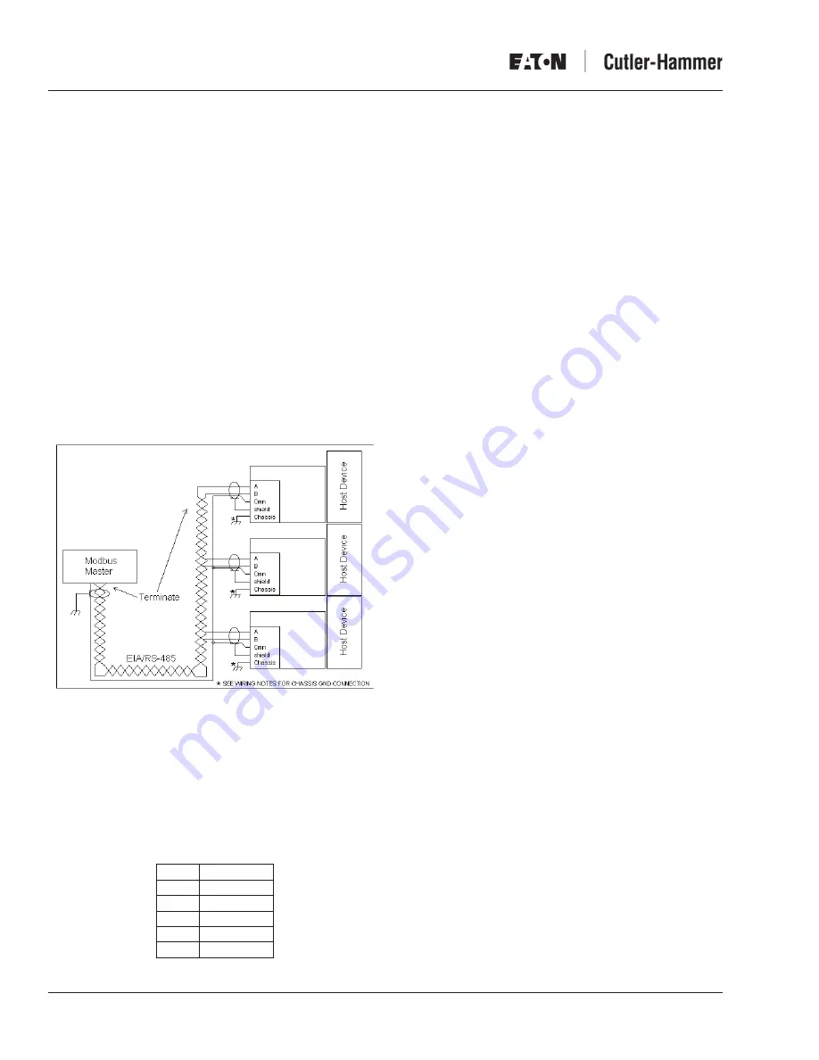
Figure 9. Typical RS-485 PONI Wiring Diagram

Connectors

RS-485 Connector

Figure 9 shows a typical Modbus network where the 

RS-485 PONI (Slave) and host devices are connected 

to the RS-485 Modbus master. A 5-pin connector pin-out 

assignment is as follows:

Pin

Signal

1

A

2

B

3

Common

4

Shield

5

Chassis

Wiring Notes:

.  A chassis ground connection is provided as part of the 

RS-485 connector. (Refer to the RS-485 Connector 

section on Page 4). It should be used only when 

mounting the RS-485 PONI to non-metallic surfaces.

2.  When mounting the RS-485 PONI to host devices where 

the mounting surfaces are tied to the chassis ground, the 

“Chassis” ground connection on the RS-485 PONI should 

not be connected. Using the metal screws provided will 

ensure a proper chassis ground connection.

3.  For maximum noise immunity, the chassis ground 

terminal should be wired to the closest system chassis 

ground with at least a 6AWG stranded copper wire. 

(See Wiring Notes  and 2.)

4.  For maximum noise immunity, the shield of the RS-485 

cable should be daisy-chained from one slave device to 

another and terminated to chassis ground at the Modbus 

master-end of the network (single-point ground).

System Capacity

The RS-485 PONI address can be set between 0 and 99 

(decimal). The maximum number of RS-485 PONIs that can 

exist.on.a.particular.network.is.99 .

If Modbus slave devices other than RS-485 PONIs exist 

within the system, and if their address can be set above 99, 

the maximum number of slave devices on the network is 247.

LEDs, Rotary Switches, DIP Switches

As part of the initial setup, the baud rate, address, and 

termination resistor must be set to their correct settings. 

These switches and indicator LEDs are described as follows:

• 

Status LED (µC) (Red)

.

The Status LED indicator lets the user know that the 

microprocessor inside of the RS-485 PONI is operating 

properly ..It.will.alternate.from.ON.for.1.second.to.OFF.for.

1.second ..

.

Other blinking patterns may be noticed in the event of 

an error detected by the RS-485 PONI. Refer to Error 

Detection in the Troubleshooting section on Page 6.

• 

RS-485 Transmit LED (TX) (Red) 

This LED will flash ON when the RS-485 PONI is 

responding to a request. The RS-485 PONI only responds 

to.requests.to.its.address .

• 

RS-485 Receive LED (RX) (Red)

.

The RX LED will flash when the RS-485 PONI detects 

that a signal is being transmitted to its address.

Summary of Contents for Cutler-Hammer

Page 1: ...66A2070 Rev B For more information visit www eaton com Effective June 2007 Instruction Leaflet 66A2070 INSTRUCTIONS FORTHE RS 485 PONI Cutler Hammer...

Page 2: ...ommunications Protocol 5 Function Codes 5 Control of Host Product 5 Register Access Configurations 6 Energy Format 6 Exception Codes 6 INCOM Protocols 6 Supported Diagnostic Sub Functions 6 Troublesho...

Page 3: ...ud rates are selectable for networking flexibility Addresses 0 99 are selectable by way of two rotary switches Status light provides indication of proper operation and also functions as an error indic...

Page 4: ...00 s style s 66D2040Gxx do not have external power supply fuses These new style meters do not require the Amp fuse included 3b Mounting to the IQ DP 4000 or IQ Data Plus II Mounting to the IQ DP 4000...

Page 5: ...the ATC 400 Attach the ribbon cable from the RS 485 PONI to the receptacle of the IQ device as shown in Figure 3 on Page 2 and firmly tighten the screws on the plug lock assembly 3f Mounting to an IQ...

Page 6: ...485 PONI to host devices where the mounting surfaces are tied to the chassis ground the Chassis ground connection on the RS 485 PONI should not be connected Using the metal screws provided will ensur...

Page 7: ...NI to an host product is listed in Figure 11 on Page 6 The Modbus master reads the INCOM product response to a pass through query using either function code 03 or 04 beginning at register 424833 61001...

Page 8: ...ction in the query is not supported by the RS 485 PONI exception code 01 is returned in the response If the data object register is illegal exception code 02 is returned in the response If the data va...

Page 9: ...PONI address Error Detection Using Status LED If the status light blinks twice in rapid ON OFF cycles followed by a 1 5 second OFF period this is an indication that the product is not being recognize...

Page 10: ...011 1998 Radiated and Conducted Emissions System Ratings Operating Temperature 20 C to 60 C Storage Temperature 20 C to 70 C Altitude 3 048 m 10 000 ft Operating Humidity 5 to 90 max non condensing En...

Page 11: ...6177 1220 1820 10 peak IB demand A 404643 406179 1222 1822 10 peak IC demand A 404645 406181 1224 1824 10 peak IG demand A 404647 406183 1226 1826 10 peak IN demand A 404649 406185 1228 1828 10 power...

Page 12: ...727 406263 1276 1876 1 x x lead KVARh 404729 406265 1278 1878 1 x x lag KVARh 404731 406267 127A 187A 1 x x net KVARh 404733 406269 127C 187C 1 x x x Energy 32 bit apparent KVAh 404735 406271 127E 187...

Page 13: ...4 Device Alarmed 21 Phase C Alarm 5 Device On 22 Neutral Alarm 6 Device Off 23 Ground Earth Alarm 7 Device Ready 24 Phase AB Alarm 8 Device Starting 25 Phase BC Alarm 9 Device Running 26 Phase CA Alar...

Page 14: ...0 Secondary status unknown Reserved 9 27 1 Secondary status is not applicable 2 Device in program mode 3 Device in test mode 4 Device disabled 5 Device disarmed 28 Product Specific Code 28 6 Controlle...

Page 15: ...izing 92 Multiple External Conditions 131 Starts Per Hour 93 Motor Bearing Temperature 132 Preferred Source 94 Load Bearing Temperature 133 Plant Exerciser 95 Auxiliary Temperature 134 Neutral Ground...

Page 16: ...y Moon Township PA 15108 4312 USA www eaton com 2005 2007 Eaton Corporation All Rights Reserved Publication No 66A2070 Rev B June 2007 Cutler Hammer Contact Information Power Quality Technical Support...

Reviews: