I.L. 17403
Page 9
Effective 9/04
Interposing Relay
START
STOP
3
2
LOW VOLTAGE RELEASE WITH
TWO-WIRE PUSHBUTTON
START-STOP OPERATION
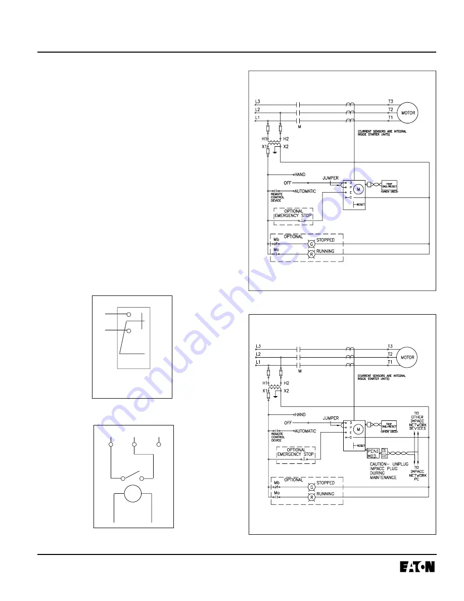
Fig. 11 Two-Wire Control
Fig. 12 Two-Wire Control with IMPACC
TWO-WIRE CONTROL
Wire as shown in Figure 11 or 12. Install a #16 or #18
AWG stranded wire jumper from 3 to P. Keep strip length
to not more than 1/4 inch.
Be sure to have jumper clear
power terminal.
Attach and route twisted pair or shielded
wires to a remote reset/trip indicator module where pro-
vided.
Without Communications
Wire control devices in the same manner as conventional
motor controllers. Add the jumper.
With Communications
Attach a WPONI communications module and connect it
to the INCOM network daisy-chain fashion as shown in
Figures 4 and 12.
When wired as shown in Figure 12 with two-wire control,
the motor cannot be started or stopped via IMPACC. The
motor starter can only be reset and data obtained via
IMPACC where two-wire control is used.
Automatic reset should not be used with two-wire
control circuit where automatic starting of the motor
may be hazardous.
3
C
GENERIC
PILOT
CIRCUIT
(PLC)
RELAY
P and/or
P
5300C76D
5300C76C


