I.L. 17403
Page 14
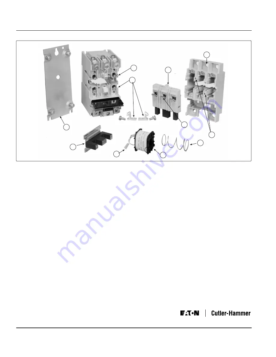
Fig. 14 Size 3 W200 Starter (Exploded View)
4201 North 27th Street
Milwaukee, WI 53216
Effective 9/04
Printed in U.S.A.
J
K
A
L
C
B
D
H
F
E
A
G
To Replace the Coil
Refer to Figure 14. Loosen the two captive arc box assembly
screws, Item G. Remove the arc box cover, Item H and
the crossbar assembly, Item B. Remove the four stationary
contacts, Item C, from the outer poles. Remove the base-
plate, Item J. Note the molded connector, Item E, containing
the two coil leads attached to a plug on the circuit board.
With a small screwdriver, lift the latch that holds this con-
nector and slide it off the plug. Loosen the four screws,
Item F, that are accessible via the deep holes under the
stationary contacts and free the plate, Item K, that holds
the E-shaped magnet. Do
not
remove the magnet from
its supporting plate, Item K. Remove the old coil, Item A.
Reassemble with the new coil positioned so that the long
projections on the coil bobbin engage the magnet and coil
leads are down. Position the return spring, Item L, between
the circular recess in the underside of the arc box and the
circular recess in the top of the coil bobbin. Attach the coil
lead connector, Item E, to its plug. Tighten the four screws
that hold the magnet supporting plate to 12-18 lb-in. Re-
place the stationary contacts, crossbar assembly, and arc
box cover, Item H. Tighten the arc box cover screws to 12-
18 lb-in.
Magnet Armature Assembly
Self-alignment and permanent air gap features of the mag-
net make replacement unnecessary. Mating pole face sur-
faces should be kept clean.
MAINTENANCE - TURN OFF POWER!
This industrial type control is designed to be installed, op-
erated, and maintained by adequately trained workmen.
These instructions to not cover all details, variations, or
combinations of the equipment, its storage, delivery, in-
stallation, checkout, safe operation, or maintenance. Care
must be exercised to comply with local, state, and national
regulations, as well as safety practices, for this class of
equipment.
To Inspect Contacts
Refer to Figure 14. Loosen the two captive arc box cover
screws accessible through holes in the nameplate and
remove the arc box cover, Item H. Remove the crossbar
assembly, Item B, containing the movable contacts. Station-
ary contacts, Item C, and movable contacts, Item D, are
visible. The silver cadmium oxide contacts need
NO
dressing or lubricant throughout their life.
Important -
Replace all contacts and springs as a group
to avoid misalignment.
To Replace Contacts
With the cross bar assembly removed, remove the two
stationary contacts, Item C, per pole. Discard all old parts,
including the magnet armature attached to the old crossbar.
Reverse the procedure to reassemble, tightening the new
stationary contact screws that hold the new stationary
contacts in place to a torque of 48-72 lb-in. Replace the
crossbar assembly, Item B, and arc box cover. Tighten
the arc box cover screws to 12-18 lb-in.


