background image

Communications 

Communicating to a PLC or Controller 

You can communicate to a PLC or controller via: 

• 

A serial connection (COM2, RS232) 

• 

An optional interface card 

• 

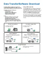
An Ethernet connection (refer to the 

Data 

Transfer/Software Download

 topic on the 

following page for more information about 
setting up an Ethernet connection) 

 
Connecting to the Serial Port (COM1) 

For convenience COM1 has been pre-configured 
with an Elo touchscreen driver to easily connect 
Cutler-Hammer touchscreen-displays to your 
PanelMate ePro. 

The driver is configured to use a mouse and the 
touchscreen at the same time. 
 

CAUTION


Your PanelMate ePro unit is not equipped with 
isolated serial ports. Ensure that there is no 
ground potential difference between your 
communication equipment and your 
PanelMate ePro unit. If there is a ground 
potential difference, your communication 
equipment will need to be isolated. 
 

Installing an Optional Interface Card 

To install optional interface cards in your 
PanelMate ePro unit, complete the following 
steps: 
1)   Disconnect power from your PanelMate ePro 

unit. 

2)   Use a Phillips screwdriver to unscrew the six 

screws located on the back of your 
PanelMate ePro unit and remove the back 
cover.  

3)   Use a Phillips screwdriver to remove the 

screw that secures the slot cover and remove 
the slot cover. 

4)   Place the interface card in the slot and secure 

the interface card with the screw from the slot 
cover. 

5)   Reassemble your PanelMate ePro unit and 

tighten the six screws located on the back of 
the unit. 


Connecting to the Serial Port (COM2) 

The external serial port may be used for 
communications with a PLC or controller.  

If you need local printing of alarms and 
messages, selection of a serial printer must be 
done with the Configuration Software. Refer to 
the Configuration Software Online Help and in the 
PanelMate Configuration Editor User's Manual for 
more information. 


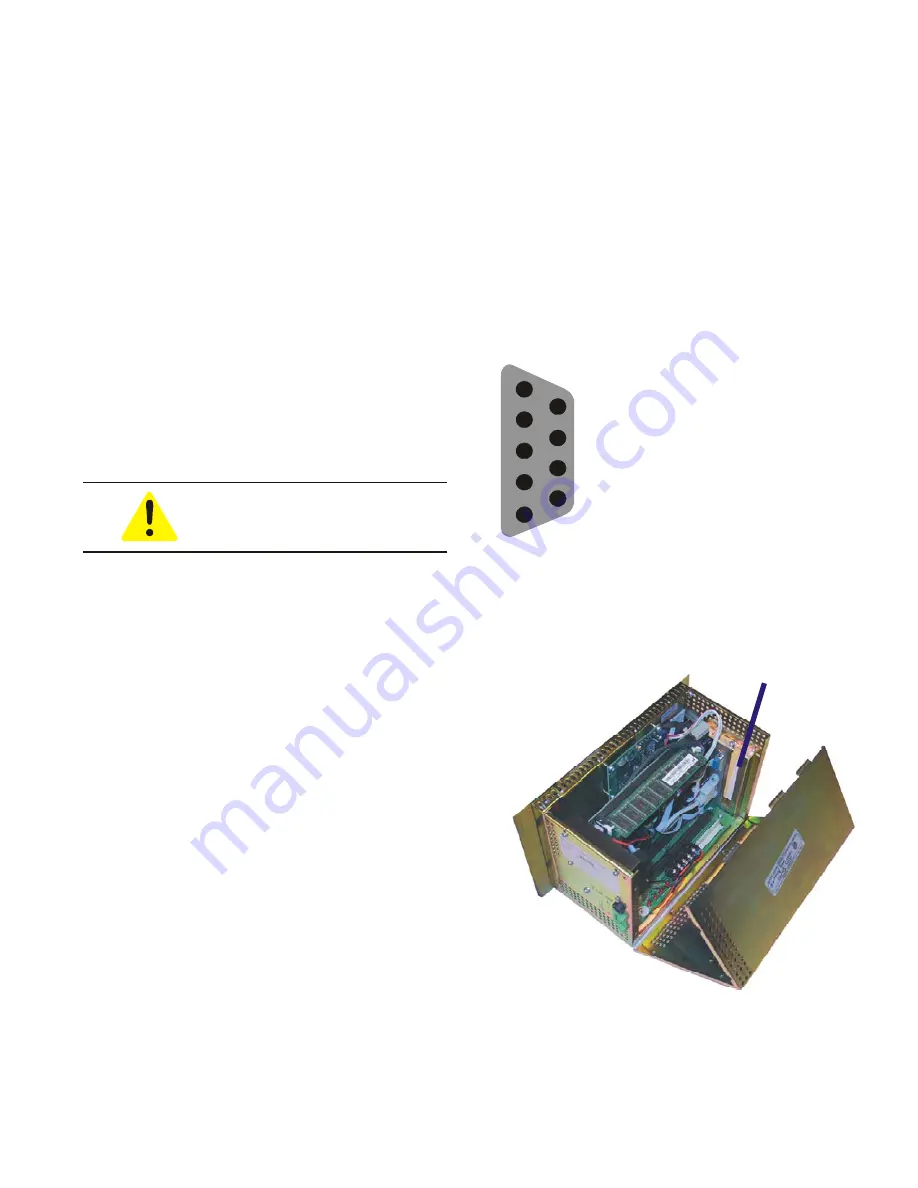
COM1 & COM2 Pinouts 

Pin Description 

2

RS232 Receive Data (Input)

3

RS232 Transmit Data (Output)

5

Signal Ground

7

RS232 Request to Send 
(Output)

8

RS232 Clear to Send (Input)

1

2

3

6

7

8

9

4

5


Optional Interface 

Card Slot


Summary of Contents for Cutler-Hammer PanelMate ePro 7500 Series

Page 1: ...PanelMate ePro 7500 Series ...

Page 2: ...ANT DOWN ONLY 800 809 2772 selection 5 5PM 8AM EST 414 449 7100 selection 5 5PM 8AM EST EMAIL CHATechSupport eaton com If you are in the US or Canada and have OI PLC IPC questions you can take advantage of our toll free line for technical assistance with hardware and software product selection system design and installation and system debugging and diagnostics Technical support engineers are avail...

Page 3: ...itions will severely shorten the unit s life Refer to Eaton s Cutler Hammer PanelMate ePro Users Guide for panel sizing and cabling recommendations The guide is available on the Cutler Hammer website www cutler hammer eaton com Mounting dimensions are shown on the Mounting Diagram page of this document The Mounting dimensions also available on the Cutler Hammer website Safety Considerations This e...

Page 4: ...Catalog Number 1219B is available for converting 120 230VAC to 24VDC CAUTION Your PanelMate ePro unit could be severely damaged if it is connected to voltages outside the range of 18 to 30VDC While your PanelMate ePro unit is fully protected against polarity reversal damage can occur if the unit is not wired correctly GND GND CAUTION If you are converting from a PanelMate powered from a 24VDC powe...

Page 5: ...on 2 environment then the external power supply must be appropriately rated Use single point grounding The external power supply and the PanelMate should be grounded to the same point This should be practiced even when the devices are located in separate enclosures This will help prevent ground loop issues Install a power supply solely for the PanelMate If the present external power supply is used...

Page 6: ...terface cards in your PanelMate ePro unit complete the following steps 1 Disconnect power from your PanelMate ePro unit 2 Use a Phillips screwdriver to unscrew the six screws located on the back of your PanelMate ePro unit and remove the back cover 3 Use a Phillips screwdriver to remove the screw that secures the slot cover and remove the slot cover 4 Place the interface card in the slot and secur...

Page 7: ... PanelMate ePro unit comes pre loaded with the M Systems DiskonKey USB driver Simply plug a DiskonKey device into the USB port of your PanelMate ePro unit and wait for the LED to stop flashing Use Explorer to find the files on the device which is listed as Removable Disk Z Note that the Iomega USB driver is also pre loaded on the ePro but it is disabled See the PanelMate ePro Users Guide for instr...

Page 8: ...Mounting Diagram Notes Dimensions are in inches Allow cable clearance on both left and right side of unit The mounting diagram is available in dwg format on Eaton s Cutler Hammer website ...

Page 9: ... interface board 1 1 A with optional communication interface board Peak Inrush Current 16 A System Ambient Temperature Operating 0 50 C 32 122 F Non operating 20 60 C 4 140 F System Vibration Operating 1 G at 10 500 Hz Non operating 1 G at 10 500 Hz System Shock Operating 30 G Non operating 30 G Relative Humidity Operating 20 90 non condensing Non operating 20 90 non condensing Altitude Operating ...

Reviews: