I.B. 48003
Page 4
Effective 11/97
LOW-VOLTAGE CONTROL COMPONENTS (Cont.)
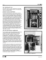
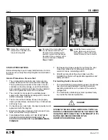
To energize the primary of the control power transformer,
the contactor must be inserted into the enclosure, the
power circuit fuses must be installed, and the isolating
switch must be closed.
For convenience during maintenance, when it may be
desirable to energize the contactor or the control circuit, a
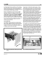
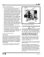
test-run plug is provided. WITH THE ISOLATING SWITCH
OPEN, disconnect the plug from the socket and plug it into
a 120 volt single-phase polarized extension cord (or 240 volt
when specified). See Figure 6.
Disconnect this temporary circuit and restore the plug to
its socket on the contactor before returning the unit to
service.
LOW-VOLTAGE CUTOFF SWITCH
Two auxiliary switches are installed behind the operating
handle housing of the isolating switch and used to
disconnect the load of a control power transformer, space
heaters, or other auxiliary circuits. Each of these auxil-
iary switches has an inductive load rating of 20 amperes
at not greater than 250 VAC. These auxiliary contacts
operate within the first five degrees of movement of the
isolating switch handle. At least one of the normally-open
contacts of these switches disconnects the control power
transformer from its load.
ISOLATING SWITCH
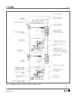
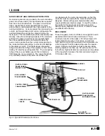
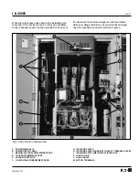
Each Ampgard
®
isolating switch is a medium-voltage,
three-pole, manually operated device. It consists of an
operating mechanism and a sliding tray mounted between
two steel end plates. The sliding tray is molded insulating
material and carries three sets of fuse jaw finger assem-
blies. One end of the fuse jaw finger assembly grips the
upper ferrule of the power fuse while the other end en-
gages the line stab. In the switch open position, the three
fuse jaw fingers are grounded.
Arc resistant and flame retarding insulating barriers are
mounted between phases and also between the two outside
poles and the isolating switch end plates.
This isolating switch is a nonload-break device. It must
never close or interrupt a power load. However, it does have
a limited capacity for interrupting the single-phase control
power and potential transformers exciting current. In terms
of transformer ratings, the maximum load is the equivalent
of an unloaded (exciting current only) 6 kVA transformer.
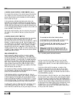
An Ampgard
®
starter is shipped with the isolating switch
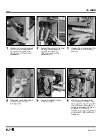
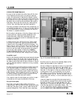
in the ON position (Figure 5, View A). The isolating
switch handle is operated by moving it through a vertical
arc from the ON to the OFF position. From the OFF
position, it can be rotated 90
o
counterclockwise to the
HORIZONTAL position, the door-open position (Figure 5,
View D).
In both the ON and OFF positions, a portion of the
handle housing extends over the door to the medium-
voltage compartment, preventing this door from being
opened. To open this door, the handle must be moved to
the HORIZONTAL position.
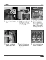
With the handle in the OFF position, up to three padlocks
can be used to lock out the switch, preventing the handle
from being moved to either the ON or the HORIZONTAL
position. This locked position prevents both unauthorized
entry into the medium-voltage compartment and acciden-
tal closing of the isolating switch while maintenance work
is being done. From the HORIZONTAL position, the
handle cannot be moved to the ON position without first
moving to the OFF position.
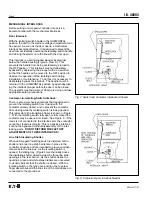
A
B
C
D
The operating handle has three distinct positions.
In the ON position (A), the isolating switch is closed, the door
is interlocked shut, and the starter may be energized.
In the OFF position (B), the isolating switch is open, the door
is interlocked shut, and the starter is de-energized and
grounded.
With the handle rotated 90° counterclockwise (C) to the
HORIZONTAL position (D), the isolating switch is open, the
starter is de-energized and grounded, and the door may be
opened.
Four Screws
t
t
t
t
Fig. 5 Isolating Switch Handle Positions


