


Step 8 - Tighten cartridge to fuse cartridge holder.
1. Tighten fuse contact flare end against fuse cartridge
holder using 50 to 70 in-lbs. torque.
2. Replace end plug on the other end of fuse cartridge
and tighten to 50 to 70 in-lbs. torque.
3. Remove end plug and ensure that petals of tulip tip
have spread uniformly.
4. Replace end plugs, applying 50 to 70 in-lbs. torque to
both connections.
Step 9 - Install fuse holder.
Use a hotstick to perform the following steps.
1. Pull pressure relief valve, holding it open until hissing
stops, and then for another five seconds.
2. Attach end of fuseholder assembly to hotstick and
insert holder assembly firmly into Bay-O-Net housing.
3. Twist locking handle so that latch engages Bay-O-Net
housing’s shoulder, and steel washer seats tightly on
end of tube of Bay-O-Net holder assembly.
Internal cartridge fuse
Internal cartridge fuses are “weak link” expulsion-type fuses
used to protect transformers and distribution systems.
Internal cartridge fuse assemblies are mounted inside
the transformer tank and are compatible for use in many
insulating liquids. See fuse manufacturer’s product literature
for maximum interrupting ratings.
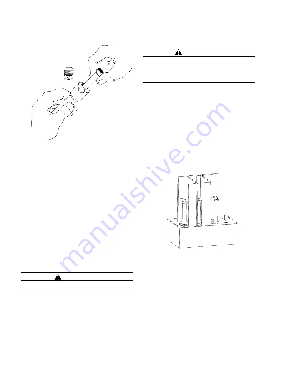
Internal cartridge fuse replacement
1. Verify that tank is grounded. De-energize transformer
from a remote upstream source. Ground all bushings
and terminals.
2. Remove tank cover as outlined in
Tank Cover Removal
and Installation
section of this manual.
3. Locate cartridge fuse assembly (see Figure 15) on back
tank wall.
4. Carefully remove all nuts that attach wire leads to fuse,
making sure not to drop nuts into the transformer tank.
Note position of all nuts, flat washers, spring washers,
etc., so that they can be reinstalled in the same
locations.
5. Replace fuses as required. Reconnect leads and re-
install washers and nuts in original locations.
6. Re-install cover as outlined in
Tank Cover Removal
and
Installation section of this manual.
Figure 14. Insert replacement fuse link.
Figure 15. Cartridge fuse assembly.
CAUTION
Visually inspect entire fuseholder assembly to ensure it
is installed properly.
WARNING
Hazardous voltage. Can cause severe injury, death, or
damage to equipment. Turn off power to transformer
before servicing internal cartridge fuses. Ground
transformer following industry accepted safe grounding
practices.
10
Three-phase pad-mounted compartmental type installation and maintenance instructions
MN202001EN August 2015


