background image

Actuator assembly replacement

To replace the actuator assembly proceed as follows:
1.  Pull yellow handle down to open switch contacts.
2.  Remove elastic stop nut, lockwasher and flatwasher 

from operating shaft.

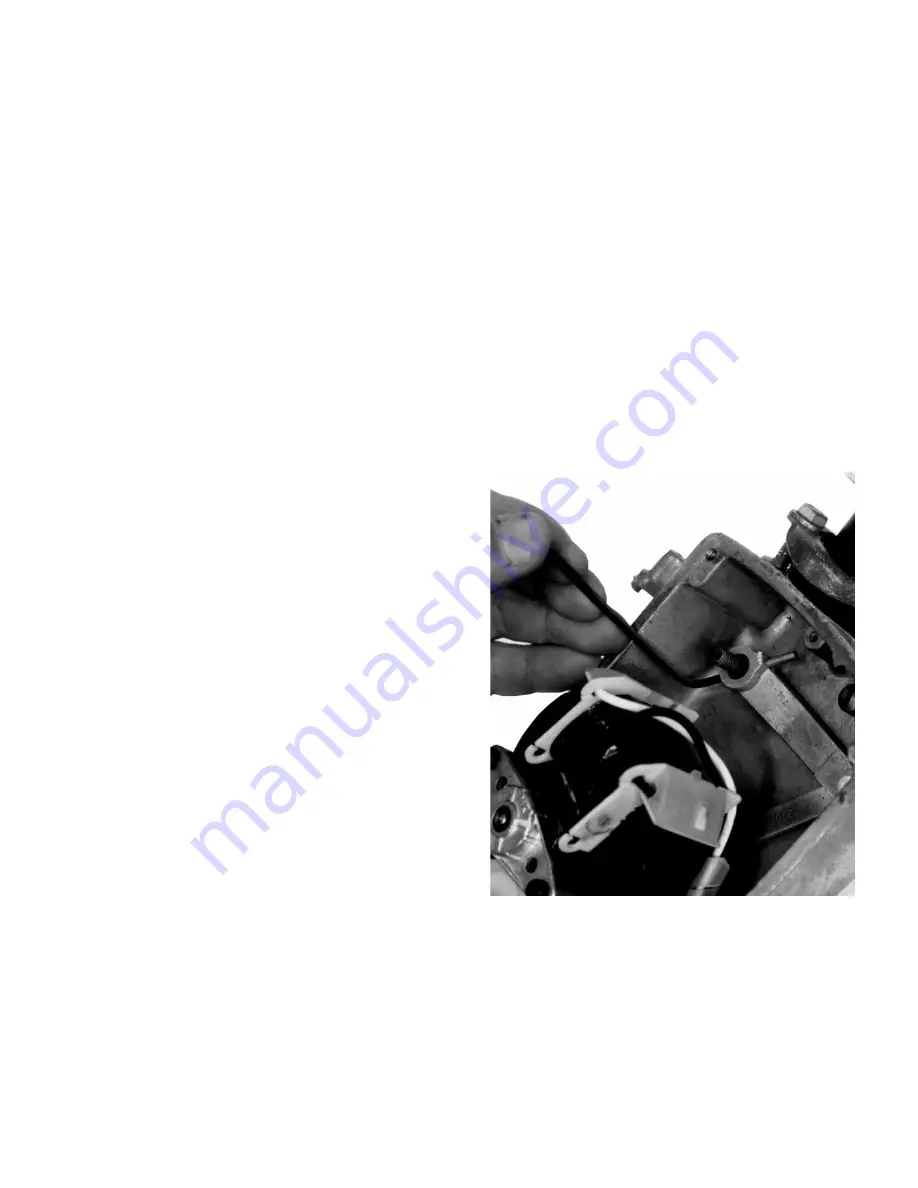
3.  With a right angle punch or allen wrench force out 

straight pin as shown in Figure 15.

4.  Disconnect wire leads from terminal strip.
5.  Remove four screws that secure actuator base plate to 

housing. Carefully lift actuator assembly from housing, 

pulling the drive lever straight from the operating shaft.

6.  Place actuator assembly in mounting position and slip 

drive lever over operating shaft. Loosely install the four 

mounting screws that secure the base plate to the 

housing.

7.  Insert straight pin through drive lever and operating 

shaft. Install flatwasher, lockwasher and elastic stop 

nut. Tighten stop nut firmly to prevent straight pin from 

backing out. Moderate force is sufficient to tighten stop 

nut. Extreme force on nut can break straight pin.

8.  Tighten four actuator assembly mounting screws.
9.  Attach wire leads to terminal strip, as shown in Figure 

12.

10.  Operate the switch electrically and check for binding. 

Check adjustment of selector switch (and holding 

switch if equipped) as described in "Shop Repair 

Procedures—Selector and Holding Switches" section.

Greasing recommendations

When a Type NR oil switch is removed from service, check 

these points in the actuator for sufficient lubrication:


Spring anchor boss


Actuator drive lever spring anchor


Mechanism shaft through cam center


Pinion gear on motor shaft and mechanism gears

Apply “MOBILGREASE 28” or a similar low-temperature 

grease to these areas. Well-lubricated mechanisms will 

reduce subsequent wear and preserve smooth actuator 

operation.

ote:

N

Grease need only be applied to these points when 

the switch is removed from service. Do not remove 

switch from service for sole purpose of applying 

lubrication to the actuator mechanism.

Head mechanism

The head mechanism requires no periodic maintenance. 

Observe the following procedure when disassembling the 

head mechanism:
1.  Remove the contact structure as described in "Shop 

Repair Procedures—Complete Contact Box Assembly" 

section.

2.  Remove the bushings as described in "Shop Repair 

Procedures—Bushings" section.

ote:

N

This step is not mandatory, but is suggested to 

simplify working on the head mechanism if a service 

rack is not available.

3.  Perform Steps 1 and 2 in "Actuator Assembly" section 

to free the actuator mechanism from the operating 

shaft.

4.  With a hammer and punch, drive out the roll pin that 

secures the reset lever to the operating shaft (Figure 

16).

5.  Remove the sleet hood cover and slip the operating 

handle spring from the reset lever. Slide out the 

operating shaft.

6.  Install new parts as required. Be sure roll pin that fixes 

reset lever to operating shaft is driven in until 3/16-inch 

of pin projects as shown in Figure 16.

Figure 15.  Removing straight pin with allen wrench.

11

TYPE NR OIL SWITCH MAINTENANCE INSTRUCTIONS

  MN230001EN   February 2016

Summary of Contents for Cooper Power NR Series

Page 1: ...od SC NR CP541000001 through CP541999999 NRV CP542000001 through CP542999999 Notice This document is also applicable to product serial numbers beginning with the characters CP57 COOPER POWER SERIES Po...

Page 2: ...T IN ANY EXISTING CONTRACT BETWEEN THE PARTIES ANY SUCH CONTRACT STATES THE ENTIRE OBLIGATION OF EATON THE CONTENTS OF THIS DOCUMENT SHALL NOT BECOME PART OF OR MODIFY ANY CONTRACT BETWEEN THE PARTIES...

Page 3: ...5 Oil condition 5 Insulation level withstand tests 5 SHOP REPAIR PROCEDURES Bushings 6 Contacts 6 Moving contacts 7 Stationary contacts 7 Moving contact arm assembly 8 Complete contact box assembly 9...

Page 4: ...sion Safety information DANGER Hazardous voltage Contact with hazardous voltage will cause death or severe personal injury Follow all locally approved safety procedures when working around high and lo...

Page 5: ...tch and inspect it thoroughly for damage incurred during shipment If damage is discovered file a claim with the carrier immediately Handling and storage Be careful during handling and storage of the s...

Page 6: ...seconds 35 30 35 30 42 36 60 50 Continuous Current Rating Amps 200 200 200 60 Load Interrupting Ability Inductive Symmetric Amps 75 100 power factor 50 75 power factor 50 power factor 200 100 50 200 1...

Page 7: ...nd other mechanical damage Paint to inhibit corrosion 3 Perform a dielectric withstand test to determine the insulation level Follow procedures in Insulation Level Withstand Tests section 4 Loosen the...

Page 8: ...on 11 If oil must be replaced drain the tank and discard the tank wall liners 12 Thoroughly clean out all sludge and carbon deposits and rinse the tank with clean oil 13 Install new tank wall liners a...

Page 9: ...ing even though it is obtained from an approved source Passing oil through a blotter press will remove free water and solid contaminants such as rust dirt and lint When filtering the oil aeration shou...

Page 10: ...r bushing gasket 4 Twist off the split aluminum ring from the old bushing and install on the new bushing assembly if ring is in good condition replace ring if damaged Note N The clamping ring cushions...

Page 11: ...tact stud Install following parts in order contact retainer flexible contact leads terminal leads flatwasher lockwasher and hex nut Tighten hex nut on bushing rod 4 With the moving contacts in the ope...

Page 12: ...4 Remove the contact arm assembly 5 Reassemble the new contact arm assembly which includes the moving contact bar to the contact box Figure 11 Contact structure removed from head mechanism Figure 8 Co...

Page 13: ...semblies if necessary as described previously E Attach terminal leads to bushing rods with flat washers lockwashers and hex nuts Actuator mechanism The actuator mechanism requires little attention Whe...

Page 14: ...es place relatively early on cam lobe and that an over travel movement of operator arm after contact actuates of approximately 3 64 inch is achieved 7 Check that main contacts open before the selector...

Page 15: ...ent lubrication Spring anchor boss Actuator drive lever spring anchor Mechanism shaft through cam center Pinion gear on motor shaft and mechanism gears Apply MOBILGREASE 28 or a similar low temperatur...

Page 16: ...on the latch lever assem bly Be sure the two shaft retainers are positioned as in Figure 17 and that the latch lever is retarded when moved away from the head casting 8 Install the contact structure a...

Page 17: ...This page intentionally left blank 13 TYPE NR OIL SWITCH MAINTENANCE INSTRUCTIONS MN230001EN February 2016...

Page 18: ...Service parts list Figure 18 Type NR oil switch service parts 14 TYPE NR OIL SWITCH MAINTENANCE INSTRUCTIONS MN230001EN February 2016...

Page 19: ...17 Caution plate SI01057 1 18 Control rating plate Decal 6A00471702 1 19 Screw sheet metal Type Z 2 x 3 16 Not required for Decal 4 20 Nameplate GR00122 1 21 Self tapping screw rd hd Type Z 10 x 3 8 8...

Page 20: ...Figure 19 Actuator and housing service parts 16 TYPE NR OIL SWITCH MAINTENANCE INSTRUCTIONS MN230001EN February 2016...

Page 21: ...66 2 11 Screw self tapping phillips pan hd Type F 6 32 x 5 8 sst 753315106062A 1 12 Actuator includes item 13 and standard selector switch GRA0381 1 Actuator repair kit 240 Vac includes item 13 and st...

Page 22: ...This page intentionally left blank 18 TYPE NR OIL SWITCH MAINTENANCE INSTRUCTIONS MN230001EN February 2016...

Page 23: ...This page intentionally left blank 19 TYPE NR OIL SWITCH MAINTENANCE INSTRUCTIONS MN230001EN February 2016...

Page 24: ...53188 United States Eaton com cooperpowerseries 2016 Eaton All Rights Reserved Printed in USA Publication No MN230001EN Eaton is a registered trademark All trademarks are property of their respective...

Reviews: