EATON Airflex WSB 11210 WCSB3 Installation Operation and Maintenance E-CLCL-11001-E October 2013
26
Caution
Before the gasket tape is covered with the wear
plate, the sealing surface should be protected to
prevent contamination from dust, dirt or oils. No
additional cleaning or liquid should be applied to the
surface of the IRON or gasket tape.
4.5.5 Inspect the new wear plates (3) and remove any
scratches or raised edges with very fine sandpaper or
steel wool. Position the smoothest side of the wear
plate on the sealing surface, being careful to align the
holes with those in the IRON.
4.5.6 Position the support rings (50) & (51) over the holes
in the wear plates (3) and install the new hex head
screws (4) and locknuts (5) provided, securing them
finger tight.
Note: the Outer support Ring (51) is comprised of two sizes. A
description of each ring and where to mount them is described in
Section 4.5.6.1.
4.5.6.1 The Outer Support Ring (51) is comprised of two
sizes. One section is shorter than the other and the
shorter section has 7 holes. The longer section has
9 holes. The longer section has two holes separated
by a larger gap than the others. The gap is to be
mounted over each coolant port. Torque the
mounting screws per Table 4 and follow the torque
tightening instructions found in Section 4.5.7.
Caution
To prevent excessive warping of the wear plate and
to endure a good seal, the following torque tightening
procedure must be followed.
4.5.7 For each wear plate being replaced, the torque
tightening instructions are as follows:
Note: The torque of the screws & nuts (4) (5) that attach the wear
plate (3) to the mounting flange (1), reaction plate (30) & pressure
plate (13) is a four step process.
(a)
Step One: For the first 16 screws, bring the initial
torque of each screw up to 33% of the torque value
shown in Table 15 using the tightening sequence
shown in Figure 12. Install and torque the remaining
screws in any reasonable crosswise pattern to 33%
of the torque value shown in Table 15.
(b)
Step Two: Repeat the sequence of torque tightening
on the first 16 screws as shown in Figure 12 and
bring each screw up to 66% of the torque value
shown in Table 15. Torque the remaining screws in
any reasonable crosswise pattern to 66% of the
torque value shown in Table 15.
(c)
Step Three: Repeat the sequence of torque tightening
on the first 16 screws as shown in Figure 12 and
bring each screw up to 100% of the torque value
shown in Table 15. Torque the remaining screws
in any reasonable crosswise pattern to 100% of the
torque value shown in Table 15.
WCSB3 Brakes
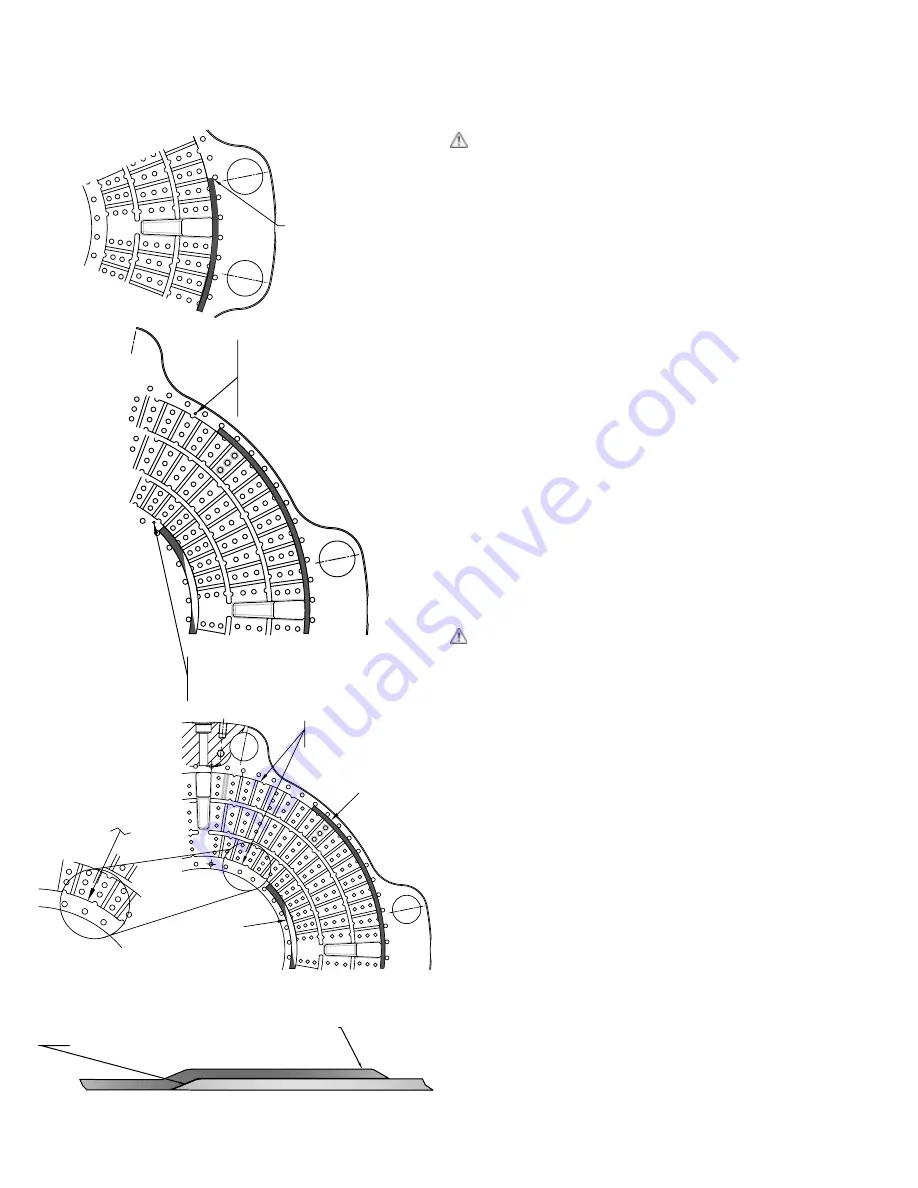
GASKET TAPE STARTS AT
CENTERLINE OF BOLT HOLE
(TAPE FOR INNER & OUTER)
Figure 9
GASKET TAPE PLACED
USING EDGE OF WATER
CAVITY AS GUIDE.
GASKET TAPE PLACED
USING EDGE OF WATER
CAVITY AS GUIDE.
GASKET TAPE
GASKET TAPE
Figure 10A
Figure 10B
Figure 11
NO PAINT ON THIS SURFACE
37.75 / 38.00 DIA. PAINT
MASK LIMIT TO OUTER CAVITY
EDGE. BOTH SIDES FOR
REACTION PLATE, ONE SIDE
FOR PRESSURE PLATE & END
PLATE.
NO PAINT ON THIS SURFACE 16.50 ID
TO INNER CAVITY EDGE. BOTH SIDES
FOR REACTION PLATE, ONE SIDE FOR
PRESSURE PLATE & END PLATE.
Tape/Gasket-Overlap a minimum of 0.44 Inches (11.2mm)
Skive ends for smooth overlap


