background image

        EATON  

Aerospace Group

    TF100-67A  March 2013                       

Rynglok Fitting System Installation Guide

6.0 

Special Consideration

6.1 

Using  the “Reversed Tool”

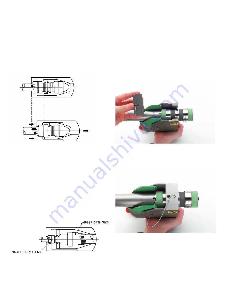
When using the RTST(X)R-01-SIZE “Reversed Tool”, care must be 

taken in positioning the tool properly onto the fitting and in position-

ing the fitting onto the tube because of the relative movement of 

the movable tool jaw. See Figure 12. The “Reversed Tool” is used in 

situations where an installation is required at or near a bulkhead or 

an adjacent fitting or structural member where the “Standard Tool” 

does not fit. This tool allows the installer the opportunity to swage 

the fitting end as close as possible to adjacent members.

Figure 12

Tool position before advancing the ring (note 

tool/tool jaw/fitting position)

                   Tool position after advancing the ring

Caution:

 Note relative movement of the whole tool with respect to 

the fitting.

6.2 

Special  Consideration When  Using The “Reversed Tool”

When using the “Reversed Tool” with reducer/expander fittings, a 

special RTST(X)R-51-SIZE “Reversed Tool” is required. The standard 

“Reversed Tool” is to be used with standard non-reducer/expander 

fitting configurations, while the special “Reversed Tool” is intended 

to be used where there is an opposite fitting end or forging body 

size greater than the dash size of the fitting end being swaged, as 

shown in Figure 13. These special “Reversed Tools” will be marked 

with a colored band and the required swage pressures identified on 

the tool body.

Warning:

 The swage pressures listed on the special “Reversed 

Tools” must be strictly adhered to, in order to prevent excessive 

tonnage applied to the fitting which may result in a damaged fitting 

or fitting failure.

6.3 

Special Considerations When Using the -20 and -24 Tools

When using the size -20 and -24 standard and reversed swage tools, 

a swage bridge attachment is used in conjunction with the standard 

hand swage tool, see Figures 14A and 14B. The swage bridge is 

to be oriented and bottomed into the swage tool detents after the 

insertion of the fitting. The swaging operation shall then proceed 

as normal. For the standard hand swage tool, the swage bridge is 

inserted into the movable jaw. 

Note:

 The swage bridge is connected 

to the hand swage tool via a flexible lanyard and should not be 

separated. Proper orientation is noted by the “Front” arrow stamped 

on top of the swage bridge and by “click” of the detents when the 

swage bridge is sitting flush on the reliefs on top of the swage tool.

Figure 14A

Swage bridge prior to placement

Figure 14B

Correct placement of swage bridge on tool

Figure 13

Using the special “Reversed Tool”

Summary of Contents for Aeroquip Rynglok Fitting System

Page 1: ...Rynglok Fitting System Installation Guide Aeroquip Rynglok Fittings...

Page 2: ...ressure 3 4 1 Pressure Level 4 0 Assembled Fitting Inspection 6 4 1 Ring Advancement Inspection 4 1 1 Insertion Inspection Mark Position 4 2 Shared Insertion Unions 4 2 1 Over Insertion Condition Fitt...

Page 3: ...tallation A suitable method such as ink stamp electro etch laser etc may be used Should the tube ends be unmarked the appropriate marks should be applied using Eaton s Aeroquip brand tube marking gaug...

Page 4: ...itting ring may be anywhere along the length of the positioning mark 2 1 1 End Fittings In general end fittings are designed to have the tube end bottomed into the fitting and do not have as much posi...

Page 5: ...nestled into the movable jaw of the tool and the front opening of the tool bottomed into the fitting body as shown in Figure 5A The tool is designed to access the fitting leg from any radial angle as...

Page 6: ...inserted to a minimum depth as shown in Figure 7 This shared insertion condition is only applicable to unions which have a through bore to allow placement onto cut lines during repair All other fitti...

Page 7: ...05 10 0 6250 3 18 11 0 6875 3 44 12 0 7500 3 56 13 0 8125 3 71 14 0 8725 3 88 15 0 9375 3 99 16 1 0000 4 15 20 1 2500 4 81 24 1 5000 5 42 Table 5 Figure 9 Defect Length Figure 10A Cutting through def...

Page 8: ...where there is an opposite fitting end or forging body size greater than the dash size of the fitting end being swaged as shown in Figure 13 These special Reversed Tools will be marked with a colored...

Page 9: ...reless Fitting Tube cut dimension as shown in Figure 16 shall use dimensions per Table 7 for proper installation Part No A 030 in Part No A 030 in R82101T03 0 602 R82101T10 979 R82101T04 0 616 R82101T...

Page 10: ...T R81101T Reducer R80151T R81171T R81191T R81151T 45 ELBOW Non Reducer R80102T R81122T R81142T R81102T Reducer R80152T R81172T R81192T R81152T 90 ELBOW Non Reducer R80103T R81123T R81143T R81103T Redu...

Page 11: ...2141T R82101T R83121T R83141T R83101T R82171T R82191T R82151T R83171T R83191T R83151T R82122T R82142T R82102T R83122T R83142T R83102T R82172T R82192T R82152T R83172T R83192T R83152T R82123T R82143T R8...

Page 12: ...ch 2013 Eaton Aerospace Group 9650 Jeronimo Road Irvine California 92618 Ph 949 452 9500 Fax 949 452 9555 www eaton com aerospace Eaton Aerospace Group Fluid Electrical Distribution Division 300 South...

Reviews: