Installation
Eaton 93E Integrated Transformer Cabinet (ITC) Installation Manual P-164000074—Rev 3
www.eaton.com/powerquality
4-5
4.2.2
Unloading the 60ITC
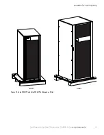
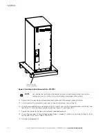
The ITC is bolted to a pallet consisting of four metal angle supports secured to two wood supports.
To remove the pallet:
1.
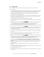
If not already accomplished, use a forklift or pallet jack to move the ITC to the installation area, or as close
as possible, before unloading from the pallet. Insert the forklift or pallet jack forks between the supports
on the bottom of the pallet (see Figure 3-6 for the ITC cabinet center of gravity measurements).
2.
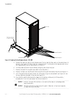
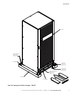
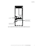
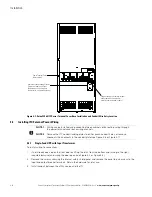
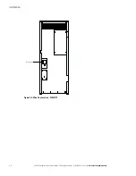
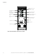
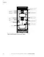
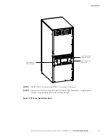
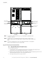
Open the front door (see Figure 4-4) by lifting the latch from the bottom and turning to the right
(counterclockwise) and swing the door open.
3.
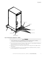
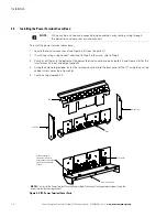
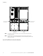
Locate the four 1/2" jacking bolts from the parts kit and install them in the threaded holes in the front and
rear supports as shown in Figure 4-4. Place a floor protector from the parts kit underneath each jacking
bolt, and screw the bolts down against them.
The floor protectors protect the floor from being marred by the jacking bolts.
4.
Loosen, but do not remove, the skid mounting bolts holding the pallet skids to the front and rear supports
(see Figure 4-4).
WARNING
RISK OF INSTABILITY. Turning the jacking bolts unevenly may cause the cabinet to become
unbalanced. To prevent tipping the cabinet, raise and lower the jacking bolts evenly.
CAUTION
CABINET MAY TIP. Raise the EBC no more than 3 mm (1/8") above the floor (just enough to allow
the removal of the pallet skids).
5.
Turn each jacking bolt consecutively, two full turns, until the pallet skids clear the floor by approximately
3 mm (1/8").
6.
Remove the hardware loosened in Step 4. Pull the two pallet skids out from under the front and rear
supports. Recycle the pallet skids and hardware in a responsible manner.
CAUTION
CABINET MAY FALL. Do not loosen the hardware attaching the front supports to the cabinet base.
The cabinet must be lowered by the jacking bolts before the supports can be removed.
7.
Carefully and evenly
lower the cabinet by turning each jacking bolt consecutively two full turns
(maximum)
until the casters contact the floor and the cabinet is no longer supported by the jacking bolts.
8.
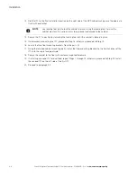
After the ITC is resting on the floor, remove the jacking bolts and floor protectors. Recycle them in a
responsible manner.
9.
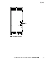
Remove the cabinet mounting bolts holding the front and rear supports to the cabinet base (see
Figure 4-4).
10. If installing the cabinet permanently, retain the cabinet mounting bolts; otherwise, recycle the bolts along
with the support brackets in a responsible manner.
11. Close the door and secure the latch.
12. If the leveling feet are not retracted, turn all four leveling feet until they are retracted as far into the cabinet
as possible.


