Smart choice for power
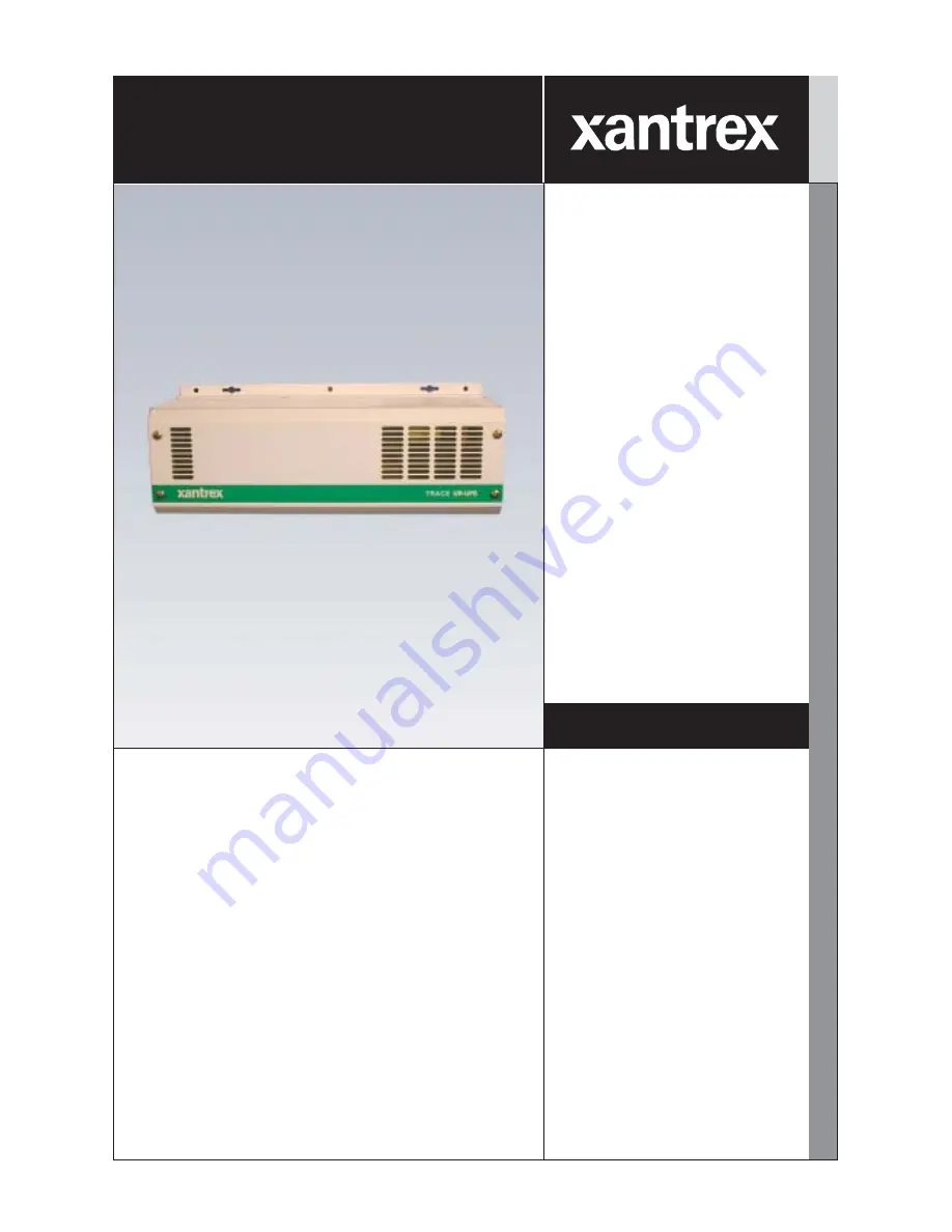
Trace Unrestricted Run-time -Uninterruptible Power System
Trace 512 UR-UPSTrace 524 UR-UPSTrace 1012 UR-UPSTrace 1024 UR-UPS
www.xantrex.com
Owner’s Manual
Page 1: ...Smart choice for power Trace Unrestricted Run time Uninterruptible Power System Trace 512 UR UPS Trace 524 UR UPS Trace 1012 UR UPS Trace 1024 UR UPS www xantrex com Owner s Manual...
Page 2: ...rademark of Xantrex International Notice of Copyright Trace Unrestricted Run Time Uninterruptible Power System UR UPS Owner s Manual October 2002 Xantrex Technology Inc All rights reserved Disclaimer...
Page 3: ...fer Sensitivity JP1 BROWNOUT 11 To Select UPS MODE Default 105 130 Vac 11 To Select GEN MODE 90 140 Vac 11 Setting Battery Type JP2 Gel Liquid 12 To Select GEL Battery Charging Default 12 To Select LI...
Page 4: ...bleshooting 29 Potential Brownout Conditions 30 Potential Problem Loads for UPS Applications 30 General Issues 30 Heavy Loads 30 Cell Phones 31 Consumer Electronics 31 Waveform Issues 31 Ceiling Fans...
Page 5: ...Maintenance B 12 Replenish Water Levels B 12 Clean Battery Cables and Posts B 12 Check Battery s State of Charge B 13 Appendix C Product Warranty and Service Information C 1 Limited Warranty C 1 What...
Page 6: ...per Enlargement 9 Figure 2 4 Jumper Placement 9 Figure 2 5 Jumper Location 10 Figure 2 6 Setting AC Transfer Sensitivity JP1 11 Figure 2 7 Battery Type Selection JP2 12 Figure 2 8 Setting Depth of Dis...
Page 7: ...talling this system This will greatly reduce the chance of accidental exposure to live circuits The unit contains more than one live circuit e g grid and or generator or batteries Power may be present...
Page 8: ...stable temperature environment Batteries should be installed in a well vented area to prevent the possible buildup of explosive gasses If the batteries are installed inside an enclosure vent its highe...
Page 9: ...essor controlled and produces a modified sine wave for use with a variety of electrical appliances including computers Basic Features and Functions Basic features and functions include the following 5...
Page 10: ...eds to be moved Record the unit s model serial number and date of purchase in the appropriate fields in section Appendix B Product Information andWarranty Model Identification and Numbering Convention...
Page 11: ...ut Voltage Output Frequency no letter 120 VAC 60 Hz E 230 VAC 50 Hz Not Available at this time Figure 1 3 Model Number Sticker Model Identification and Numbering Conventions continued DR512 UR UPS DR5...
Page 12: ...4 1 0 Introduction 2002 Xantrex Technology Inc All Rights Reserved P N 975 0049 01 01 Rev A 10 2002 Notes...
Page 13: ...ng of the AC input and output adequate wire of appropriate size and length to comply with local electrical standards and regulations Appropriately sized battery or battery bank to support the desired...
Page 14: ...all 2 Measure the desired height from the floor for the unit to be mounted 3 Place a pre cut 2x4 on the marked location and drill pilot holes through the 2x4s and studs 4 Secure the 2x4 with 10 wood s...
Page 15: ...049 01 01 Rev A 10 2002 Figure 2 1 Wall mounting the Trace UR UPS Wallboard Wall Studs 16 inches on center 2x4 mounting supports 5 15 16 c c TRACE UR UPS 7 1 8 7 1 8 14 10 5 Keyhole Slots X4 Mounting...
Page 16: ...Removing the four Phillips screws from the top of the unit 2 Lift the cover off the unit Replacing the Top Cover 1 Set the cover back on the unit ensuring the guide feet insert properly into the base...
Page 17: ...it that fit over two pins A jumper contains an internal conductor that joins the two pins completing a circuit When the jumper is removed the circuit is interrupted When a jumper is not connecting th...
Page 18: ...tion CAUTION Be extremely careful when removing and or installing the jumpers Do NOT bend the pins as permanent damagetothe circuit board can occur Jumper Location r e p m u J D I n o i t c n u F t l...
Page 19: ...e from 90 140 Vac before the unit switches to batteries In the UPS MODE the tolerance for utility supplied power is from 105 130 Vac To Select UPS MODE Default 105 130 Vac JUMPER ON Place the jumper o...
Page 20: ...ated on Table 2 1 on page 9 use different batteries To Select GEL Battery Charging Default JUMPER ON Place the jumper on both contact pins To Select LIQUID Battery Charging JUMPER OFF Remove the jumpe...
Page 21: ...ischarged to 11 7 Vdc for a period of five minutes This causes less stress on the batteries resulting in longer battery life The unit s run time will be shorter in this mode and the batteries will rec...
Page 22: ...ice or unless told to remove it by an authorized Xantrex Customer Service Representative JUMPER ON Default position N A JUMPER OFF N A Figure 2 9 Setting Option B JP4 Not Used at this time Jumper OFF...
Page 23: ...the ground wire to the negative terminal on the battery 3 Run another 8 AWG ground wire from the battery s negative terminal to the main utility panel s ground bar or grounding electrode WARNING BE V...
Page 24: ...aw by the unit s efficiency Add a 25 safety margin to comply with code requirements The term free air is defined by the NEC as cabling that is not enclosed in a conduit or a raceway Cables enclosed in...
Page 25: ...UR UPS 6 Connect the second positive battery cable connected to the DC fuse and disconnect directly to the positive battery terminal Ensure the cable s lug is flush against the battery s terminal 7 C...
Page 26: ...XJ OXPLQXP 0HFKDQLFDO XJ R QRW SODFH DQ WKLQJ EHWZHHQ EDWWHU FDEOH OXJ DQG WKH EDWWHU WHUPLQDO VXUIDFH VVHPEOH H DFWO DV VKRZQ DWWHU 7HUPLQDO 6XUIDFH DWWHU DEOH XJ DWWHU DEOH XJ DWWHU 7HUPLQDO 6XUIDF...
Page 27: ...branch circuit breaker CAUTION Do not connecttheAC input plug into the unit s output receptables Figure 2 13 AC Input Plug and Output Receptacles AC Input Plug AC Grounding AC input plug must be conn...
Page 28: ...ut follow the directions on pages 21 through 22 Use a minimum 14 AWG solid wire for all input and output wiring Check with your local electrical codes for absolute compliance on this wire size Knockou...
Page 29: ...0 mm 4 Connect the green yellow ground wire to the lower terminal on the main PC board 5 Connect the blue or white neutral wire to the center terminal on the main PC board 6 Connect the brown or black...
Page 30: ...he main electrical utility box 3 Strip all wires back approximately 3 8 inch 10 mm 4 Connect the green yellow ground wire to the lower terminal on the main PC board 5 Connect the blue or white neutral...
Page 31: ...en STATUS LED indicates whether or not the unit is active Yellow CHARGER status LED indicates that the unit is in charger mode Red Yellow ERROR status LED indicates an error condition See Table 3 1 fo...
Page 32: ...on the control panel CHG Mode When no AC power is present this is the OFF position for the unit and will not provide backup power to the connected loads When the unit is in CHG mode and it detects AC...
Page 33: ...s b a k l u b w o l l e Y d i l o S e d o m t a o l f e h t n i g n i g r a h c s i r e g r a h c e h T r o r r E w o l l e Y d e R w o l l e Y d i l o S N O I T I D N O C Y R E T T A B H G I H e g a...
Page 34: ...the bulk voltage setting is reached 14 3 Vdc for gel batteries and 14 7 Vdc for liquid batteries The charger then switches to absorption mode During this stage of charging the automatic cooling fan w...
Page 35: ...tomatic transfer relay rated at 15 amps and protected by a 15 amp circuit breaker When the AC utility or generator power returns there is a built in 20 second delay before the unit switches from inver...
Page 36: ...28 3 0 Operation 2002 Xantrex Technology Inc All Rights Reserved P N 975 0049 01 01 Rev A 10 2002 Notes...
Page 37: ...n o c e s d r o c r e w o p C A s r e t r e v n I t u p t u o s r e t r e v n i e h t o t n i d e g g u l p e l c a t p e c e r d r o c e n i l C A g u l p n U e g r a h c t o n l l i w s e r e t t a...
Page 38: ...e load with a high inrush current demand A unit that has incorrectly sized DC cables poor connections or failing batteries is like a house with a substandard foundation Potential Problem Loads for UPS...
Page 39: ...more noise than when connected to utility power High speed fans tend to operate normally Clocks The unit s crystal controlled oscillator keeps the frequency accurate to within a few seconds a day howe...
Page 40: ...echargeable device monitor its temperature for 10 minutes to ensure it does not become abnormally hot Excessive heat will indicate that it is incompatible with the unit Potential Problem Loads related...
Page 41: ...unit will revert to idle mode and the light will go off When the light cools its load will again exceed the threshold and the cycle will repeat Fluorescent Bulbs These work the opposite of incandesce...
Page 42: ...e search sensitivity threshold is set higher than the combined loads an auxiliary load must be used to bring the unit out of search mode before the appliances will turn on If the sensitivity threshold...
Page 43: ...H 0 6 z H 0 6 z H 0 6 t u p t u O s u o u n i t n o C C A s p m a 2 4 C A s p m a 2 4 C A s p m a 3 8 C A s p m a 3 8 g n i t a R s m 0 0 1 y t i l i b a p a C e g r u S s p m a 0 2 s p m a 0 2 s p m...
Page 44: ...o n o N s e r u t a r e p m e t e g a r o t s C 0 7 o t C 5 5 F 7 6 1 o t F 7 6 y t i d i m u H e g a r o t S g n i t a r e p O s t i m i L g n i s n e d n o c n o N H R 5 9 0 2 S N O I T A C I F I C...
Page 45: ...teries starting and deep cycle with several different types of chemistries Batteries can be either sealed or non sealed vented The battery types recommended for use with this unit are Flooded Lead Aci...
Page 46: ...and AGM Both gel cell and absorbed glass mat AGM batteries are virtually maintenance free making them ideal for inverter applications Since the batteries are completely sealed they can be mounted in a...
Page 47: ...an 50 of their capacity on a regular basis Discharging up to 80 is acceptable on a limited basis such as a prolonged utility outage Totally discharging a battery results in permanent damage and reduce...
Page 48: ...on the appliances then use the formula WATTS VOLTS x AMPS Then divide the calculated wattage of the load by the system battery voltage to determine the amperage the load will draw from the batteries A...
Page 49: ...ng steps to calculate the battery bank capacity requirements Use the blank table on the next page to enter the values for your system A sample table is shown below NOTE Motors typically require 3 6 ti...
Page 50: ...5 2 0 3 1 8 n o i s i v e l e T 0 0 1 4 7 0 0 4 r e h s a W 5 7 3 1 2 7 0 1 r o t a r e g i r f e R 0 6 1 3 0 8 4 4 2 7 0 4 8 3 r e n a e l C m u u c a V 0 0 2 1 1 1 1 7 1 9 3 1 5 7 1 4 5 1 4 3 8 0 3...
Page 51: ...OURS REQUIRED Step 5 column and enter this number into the TOTAL DAILY WATT HOURS REQUIRED Step 6 column in the second table Step 7 Multiply the TOTAL DAILY WATT HOURS REQUIRED Step 6 figure by the nu...
Page 52: ...u R d e s u s r u o H x y a d h c a e d e s u s y a D x k e e w h c a e e g a r e v A 7 r u o H t t a W y l i a D t n e m e r i u q e R 6 p e t S 7 p e t S 8 p e t S 9 p e t S 0 1 p e t S t t a W y l...
Page 53: ...0 0 4 r e t u p m o C 0 0 3 0 0 2 r e t s a o T 0 0 0 1 t c a p m o c e v a w o r c i M 0 0 8 0 0 6 e t a l P t o H 0 0 8 1 e z i s l l u f e v a w o r c i M 0 0 5 1 r e y r D r e h s a W 0 0 0 1 5 7...
Page 54: ...ition the batteries can be wired to provide additional run time The various wiring configurations are as follows Series Wiring batteries in series increases the total bank output voltage This voltage...
Page 55: ...t Battery Configurations continued Series Parallel Series parallel configurations increase both the battery voltage to match the unit s DC requirements and run time for operating the AC loads 12 volt...
Page 56: ...batteries frequently when performing an equalize charge and add water if necessary Always follow the safety steps covered in the front of the manual Clean Battery Cables and Posts Battery posts must b...
Page 57: ...ach battery To determine the individual cell voltage divide the voltage by the number of cells in the battery i e 12 6 volts divided by 6 cells 2 1 volts per cell If a greater difference is measured t...
Page 58: ...Battery s State of Charge continued f o t n e c r e P e g r a h C l l u F e g a t l o V m e t s y S l l e C l a u d i v i d n I e g a t l o V V 2 1 V 4 2 0 0 1 7 2 1 4 5 2 2 1 2 0 9 6 2 1 2 5 2 0 1 2...
Page 59: ...d that it is covered by this Limited Warranty Xantrex will at its option use new and or reconditioned parts in performing warranty repair and building replacement products Xantrex reserves the right t...
Page 60: ...olicy described in your product manual For some products Xantrex maintains a network of regional Authorized Service Centers Call Xantrex or check our website to see if your product can be repaired at...
Page 61: ...ternally or externally or damaged from improper use or use in an unsuitable environment b the product if it has been subjected to fire water generalized corrosion biological infestations or input volt...
Page 62: ...WISE INCLUDING WITHOUT RESTRICTION ANY IMPLIED WARRANTY OR CONDITION OF QUALITY MERCHANTABILITY OR FITNESS FOR A PARTICULAR PURPOSE ANY IMPLIED WARRANTY OF MERCHANTABILITY OR FITNESS FOR A PARTICULAR...
Page 63: ...al damages so the above limitation s or exclusion s may not apply to you This Limited Warranty gives you specific legal rights You may have other rights which may vary from state to state or province...
Page 64: ...correct factory Ship To address Products must also be shipped prepaid Product shipments will be refused and returned at your expense if they are unauthorized returned without an RMA number clearly mar...
Page 65: ...unit can be shipped post office boxes are not acceptable a contact telephone number where you can be reached during work hours and a brief description of the problem 3 Ship the unit prepaid to the add...
Page 66: ...01 01 Rev A 10 2002 Service Information Model Number Serial Number Purchase Date Problem Include a telephone number where you can be reached during business hours and a complete return shipping addres...
Page 67: ...ion 10 12 BatteryVoltage Meter 23 C circuit board 10 Configuration Options 8 Connection to the Battery 17 18 control panel 23 D DCWiring 15 16 17 18 Depth of Discharge 8 10 13 deep 13 shallow 13 F Fea...
Page 68: ...de 32 33 34 Confirming Search Mode Operation 32 Potential Problem Loads related to Search Sense Mo 32 33 34 Other loads 34 SettingACTransfer Sensitivity 11 Setting BatteryType 12 Setting Depth of Disc...
Page 69: ......
Page 70: ......
Page 71: ......
Page 72: ...Xantrex Technology Inc 1 800 670 0707 Toll Free 1 604 422 2777 Direct 1 604 420 2145 Fax www xantrex com Printed in the USA 975 0049 01 01 Rev A 10 2002...