


Sync Control for Eaton 9395P and 93PM
28
User’s and Installation Guide
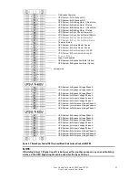
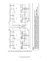
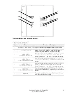
Figure 4-2 Synchronization Reference Control
NOTES:
•
The Synchronization Reference Control relays are shown under normal conditions.
Both bypass sources are available and are in synchronization.
•
Dashed switch position of Synchronization Reference Control Relay 1 shows UPS
System-A in the non-master system mode.
•
Dashed switch position of Synchronization Reference Control Relay 2 shows UPS
System-B in the non-master system mode.
•
At any given time, only one of the UPS systems can be in the non-master system
mode.
4.3
Operation
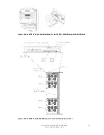
Perform the following procedures to set up the Eaton Sync Control for operation with your
system. See Figure 4-3 and Table 4-1 for the location and explanation of the controls and
indicators on the Eaton Sync Control.
1.
Place both UPS systems in normal operating mode. Refer to the applicable Eaton 9395P or
93PM UPS Installation and Operation Manual. The manuals are listed in Paragraph1.3 on
page 7.
2.
Press the Lamp Test pushbutton to verify all indicators illuminate and are working correctly.
3.
Determine which system load bus (A or B) will be used as the master synchronization
source. Set the Preferred Source Selector switch to this load bus.
4.
Press the Load Sync Enable pushbutton to enable the automatic synchronization control. The
pushbutton illuminates when the synchronization control is enabled.
5.
To disable the automatic synchronization control, press the Load Sync Enable pushbutton
and verify that the indicators, including the Load Sync Enable pushbutton, are off.