


Sync Control for Eaton 9395P and 93PM
18
User’s and Installation Guide
3.2
Installation and Wiring with an Eaton 93PM UPS
To install and wire:
7.
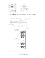
Install the Eaton Sync Control panel to the selected mounting location.
See Figure 2-1 on page 9 for mounting hole dimensions and Figure 2-2 on page 9 for cable
entrance locations.
8.
Unfasten the front door latches and swing the door open.
9.
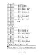
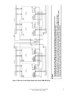
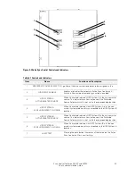
Complete all control wiring interconnections using Table 3-4 on page 19 or Table 3-5 on page
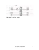
20 for wiring requirements.Figure 3-6 on page 21 shows the Eaton Sync Control TB1
terminal block and ground terminal locations. Figure 3-7 on page 22 shows the TB1 terminal
block wiring detail.
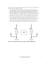
Figure 3-8 on page 23 shows the sync control interface of the 93PM. Figure 3-9 on page 23
shows the typical locations of the UPS Inputs, Outputs and X11 terminal blocks. Figure 3-10
on page 24 shows the X11 detail.
Refer to the applicable Eaton 93PM UPS Installation and Operation Manual for
UPS cabinet
terminal locations and assignments, termination requirements, cable landing locations, and
terminal access instructions.
10.
Verify the jumper is installed between Eaton Sync Control terminal TB1-72 and TB1-73 (see
Figure 3-7 on page 22).
11.
If applicable, complete all customer remote monitoring system wiring interconnections using
Table 3-6 on page 21 for wiring requirements.
Figure 3-7 on page 22 shows the TB1 terminal block wiring detail.
12.
When all wiring is complete, close the door and secure the latches.