


Sync Control for Eaton 9395P and 93PM
15
User’s and Installation Guide
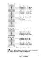
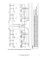
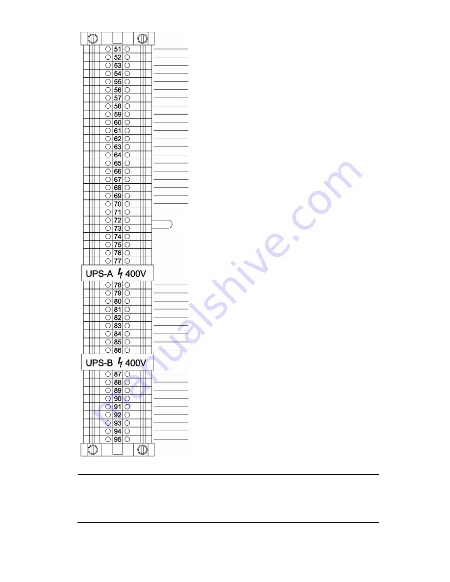
Figure 3-2 Eaton Sync Control TB1 Terminal Block Detail for 9395P
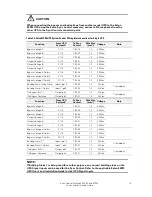
NOTE:
If Building Alarm 1 is being used for another purpose, any unused building alarm on the
UPS TB3 terminal board can be used for the Sync Control. Refer to the applicable Eaton
9395P UPS User’s and Installation Guide listed in paragraph 1.3 on page 7 for the UPS
TB3 terminal assignments.
On Bypass Common
UPS System-A
─
On Bypass NO
UPS System-B
─
On Bypass NO
UPS System-B
─
Reference Voltage Phase B
UPS System-B
─
Reference Voltage Phase A
UPS System-B
─
Reference Voltage Phase C
UPS System-A
─
Building Alarm 1 (See Note)
UPS System-B
─
Building Alarm 1 (See Note)
UPS System-A
─
Sync Control Alarm NO
UPS System-A
─
Sync Control Alarmt Return
UPS System-B
─
Sync Control Alarm NO
UPS System-B
─
Sync Control Alarm Return
Common Return
UPS System-A
─
Active Master Source
UPS System-B
─
Active Master Source
UPS System-A
─
Synchronized to Load B
UPS System-B
─
Synchronized to Load A
Common Return
Load Sync Enabled
Jumper wire
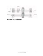
UPS System-A
─
Building Alarm 1 Return
UPS System-B
─
Building Alarm 1 Return
UPS System-B
─
Output Voltage Phase B
UPS System-B
─
Output Voltage Phase A
UPS System-B
─
Output Voltage Phase C
UPS System-B
─
Bypass Voltage Phase B
UPS System-B
─
Bypass Voltage Phase A
UPS System-B
─
Bypass Voltage Phase C
UPS System-
A─
Reference Voltage Phase B
UPS System-
A─
Reference Voltage Phase A
UPS System-
A─
Reference Voltage Phase C
UPS System-
A─
Output Voltage Phase B
UPS System-
A─
Output Voltage Phase A
UPS System-
A─
Output Voltage Phase C
UPS System-
A─
Bypass Voltage Phase B
UPS System-
A─
Bypass Voltage Phase A
UPS System-
A─
Bypass Voltage Phase C
UPS System-A
─
Bypass Available (Option)
UPS System-B
─
Bypass Available (Option)