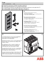
background image

36

Instruction Book    

IB182017EN   February 2017   www.eaton.com

5kV, 7.5kV, & 15kV DHP-VR

Replacement Circuit Breaker

6.3   VACUUM INTERRUPTER INTEGRITY TEST

Vacuum interrupters used in Type VR-Series circuit breakers are 

highly reliable interrupting elements. Satisfactory performance of 

these devices is dependent upon the integrity of the vacuum in 

the interrupter and the internal dielectric strength. Both of these 

parameters can be readily checked by a one minute AC high 

potential test. (See Table 6.1 for appropriate test voltage.) During this 

test, the following warnings must be observed:

 WARNING

APPLYING ABNORMALLY HIGH VOLTAGE ACROSS A PAIR OF CONTACTS 

IN VACUUM MAY PRODUCE X-RADIATION. THE RADIATION MAY 

INCREASE WITH THE INCREASE IN VOLTAGE AND/OR DECREASE IN 

CONTACT SPACING. X-RADIATION PRODUCED DURING THIS TEST 

WITH RECOMMENDED VOLTAGE AND NORMAL CONTACT SPACING 

IS EXTREMELY LOW AND WELL BELOW MAXIMUM PERMITTED BY 

STANDARDS. HOWEVER, AS A PRECAUTIONARY MEASURE AGAINST 

POSSIBILITY OF APPLICATION OF HIGHER THAN RECOMMENDED VOLTAGE 

AND/OR BELOW NORMAL CONTACT SPACING, IT IS RECOMMENDED THAT 

ALL OPERATING PERSONNEL STAND AT LEAST ONE METER AWAY IN 

FRONT OF THE BREAKER.

 WARNING

DC HI-POTENTIAL TESTS ARE NOT RECOMMENDED BY EATON. DO NOT 

APPLY DC AT ANY LEVEL TO VR-SERIES POWER CIRCUIT BREAKERS

With the breaker open and securely sitting on the floor, connect 

all top/front primary studs (bars) together and the high potential 

machine lead. Connect all bottom/rear studs together and the high 

potential return lead. Do not ground them to the breaker frame. Start 

the machine at zero potential, increase to appropriate test voltage 

and maintain for one minute.
Successful withstand indicates that all interrupters have satisfactory 

vacuum level. If there is a breakdown, the defective interrupter or 

interrupters should be identified by an individual test and replaced 

before placing the breaker in service.
After the high potential is removed, discharge any electrical charge 

that may be retained, particularly from the center shield of vacuum 

interrupters. To avoid any ambiguity in the AC high potential test due 

to leakage or displacement (capacitive) current, the test unit should 

have sufficient volt-ampere capacity. It is recommended that the 

equipment be capable of delivering 25 milliamperes for one minute.
The current delivery capability of 25 mA AC applies when all three 

VI’s are tested in parallel. If individual VI’s are tested, current 

capability may be one third of this value.

6.4   CONTACT EROSION AND WIPE

Since the contacts are contained inside the interrupter, they remain 

clean and require no maintenance. However, during high current 

interruptions there may be a minimal amount of erosion from the 

contact surfaces. To determine contact erosion, close the breaker 

and observe the vacuum interrupter moving stem from the rear of 

the breaker. If the mark on each stem is visible, erosion has not 

reached maximum value thus indicating satisfactory contact surface 

of the interrupter. If the mark is not visible, the vacuum interrupter 

assembly must be replaced (Figure 6.1 and 6.2).
The adequacy of contact wipe can be determined by simply 

observing the vacuum interrupter side of the operating rod assembly 

on a closed breaker. Figures 6.3 and 6.4 show the procedure for 

determining the contact wipe. It maybe necessary to use a small 

mirror and flashlight to clearly see the “T” shape indicator. If the 

wipe is not adequate, the vacuum interrupter assembly (Pole Unit) 

must be replaced. Field adjustment is not possible.

 WARNING

FAILURE TO REPLACE A VACUUM INTERRUPTER ASSEMBLY WHEN 

CONTACT EROSION MARK IS NOT VISIBLE OR WIPE IS UNSATISFACTORY, 

WILL CAUSE THE BREAKER TO FAIL TO INTERRUPT AND THEREBY CAUSE 

PROPERTY DAMAGE OR PERSONNEL INJURY.

Vacuum Interrupter Integrity Test Voltage

Breaker Rated Maximum Voltage

AC 60Hz

Up to and including 15.0 kV

27 kV

Figurt 6.1. Vacuum Inttrrupttr Showing Contact Erosion 

Indicator With Brtaktr Optn  


(Shown htrt for clarity purposts only)

Figurt 6.2. Vacuum Inttrrupttr Showing Contact Erosion 

Indicator With Brtaktr Clostd  


(Indicators art chtcktd only whtn brtaktr is clostd.)

Summary of Contents for 50DHP-VR

Page 1: ...February 2017 Instruction Book IB182017EN 5kV 7 5kV 15kV DHP VR Replacement Circuit Breaker Supersedes I B 6513C80G Effective 5kV DHP VR 1200A Shown...

Page 2: ...to be covered by these instructions If further information is desired by purchaser regarding his particular installation operation or maintenance of particular equipment contact an Eaton representati...

Page 3: ...RLOCK 25 4 7 3 ANTI CLOSE INTERLOCK 25 4 7 4 FLOOR TRIPPING AND CLOSING SPRING RELEASE INTERLOCKS 25 4 7 5 RAIL LATCH 25 4 8 MISCELLANEOUS ITEMS 25 4 8 1 GROUNDING CONTACT 25 4 8 2 MOC AND TOC OPERATI...

Page 4: ...s VIBE is a digital supplemental booklet featuring user interactive content and informative videos intended to assist with the maintenance of the VR Series circuit breaker The VIBE document is availab...

Page 5: ...78 132 4 16 350 1200 2000 3000 50DHP350 1 19 19 60 41 49 78 132 75DHP VR 7 2 500 1200 2000 3000 75DHP500 1 25 36 95 33 41 66 111 75DVP VR 7 2 500 1200 2000 75DVP500 1 25 36 95 33 41 66 111 150DHP VR...

Page 6: ...kV DHP VR Replacement Circuit Breaker Table 2 DHP VR 5kV 250 MVA Rating Dimensions Breaker Type Existing Breaker Rated Continuous Current at 60 Hz Amps A B C D E F G H I 50DHP VR 250 250U 1200 2000 48...

Page 7: ...15kV DHP VR Replacement Circuit Breaker Table 3 DHP VR 5kV 350 MVA Rating Dimensions Breaker Type Existing Breaker Rated Continuous Current at 60 Hz Amps A B C D E F G H I 50DHP VR 350 1200 2000 57 1...

Page 8: ...V 7 5kV 15kV DHP VR Replacement Circuit Breaker Table 4 DHP VR 5kV 350 MVA Rating Dimensions Breaker Type Existing Breaker Rated Continuous Current at 60 Hz Amps A B C D E F G H 50DHP VR 350 3000 61 1...

Page 9: ...Amps A B C D E F G 75DHP VR 500 1200 2000 3000 60 75 31 25 10 00 34 81 10 00 19 75 20 69 150DHP VR 500 1200 2000 3000 60 75 31 25 10 00 34 81 10 00 19 75 20 69 150DHP VR 750 1200 2000 3000 60 75 31 2...

Page 10: ...V 15kV DHP VR Replacement Circuit Breaker Table 6 DHP VR 15kV Ratng Dimensions Breaker Type Existing Breaker Rated Continuous Current at 60 Hz Amps A B C D E F 150DHP VR 50G 1200 2000 3000 73 72 31 00...

Page 11: ...njury and or property damage Do not work on a breaker with the secondary test coupler engaged Failure to disconnect the test coupler could result in an electrical shock leading to death personnel inju...

Page 12: ...ch moves the circuit breaker into and out of the cell The original OEM racking handle will interface with the VR Series replacement breaker racking mechanism and is therefore not provided as part of t...

Page 13: ...this initial check leave the closing springs discharged and breaker contacts open Outdoor storage is NOT recommended If unavoidable the outdoor location must be well drained and a temporary shelter fr...

Page 14: ...VR 250 1200A Shown Front External View 1 Pull Push Handle 6 Code Plate 11 Push To Open Button 2 Operations Counter 7 Secondary Contact Operating Rod 12 Racking Operating Shaft 3 Breaker Contact Statu...

Page 15: ...ing Outer Phase Barrier Removed For Demonstration Purposes Rear External View 1 Lifting Point 5 Phase Barrier 9 Racking Nut Housing 2 Vacuum Interrupter 6 V flex Current Connectors 10 Secondary Discon...

Page 16: ...DHP VR 500 2000A Shown Front External View 1 Pull Push Handle 5 Code Plate 9 Spring Charged Discharged Indicator 2 Operations Counter 6 Secondary Engaging Handle 10 Racking Operating Shaft 3 Breaker C...

Page 17: ...igure 3 3 d Rear External View of 7 5 and 15kV DHP VR 150DHP VR 500 2000A Shown Rear External View 1 Lifting Point 4 Guide Channel 7 Snubber Bolt 2 Racking Nut Housing 5 Phase Barrier 8 Secondary Disc...

Page 18: ...VR 50G Front External View 1 Operations Counter 5 Secondary Engaging Handle 9 Spring Charged Discharged Indicator 2 Breaker Contact Status Indicator 6 Removable Faceplate 10 Racking Operating Shaft 3...

Page 19: ...rcuit Breaker Figure 3 3 f Rear External View of 15kV DHP VR 50G Rear External View 1 Lifting Point 4 Phase Barrier 7 Racking Nut Housing 2 MOC Switch Operating Mechanism 5 Primary Disconnect Contact...

Page 20: ...g a restrike across the gap of the open contacts 4 1 1 THE INTERRUPTER ASSEMBLY Each interrupter is assembled at the factory as a unit to assure correct dimensional relationships between working compo...

Page 21: ...ADJUSTMENTS OF CONTACT WIPE AND STROKE ALL SUCH ADJUSTMENTS ARE FACTORY SET AND SHOULD NOT BE ATTEMPTED IN THE FIELD 4 2 PHASE BARRIERS Phase barriers are sheets of insulation located between the inte...

Page 22: ...In Figure 4 16 a the breaker is open and the closing springs are discharged In this state the trip latch is disengaged from the trip D shaft unlatched After the closing springs become charged the tri...

Page 23: ...pt between Test and Connect positions OPERATION C and NO C and NC C and NO C and NO C and NC C and NO Brown Switch Black Switch Black Switch Brown Switch SWITCH TERMINAL LS1 bb LS2 aa LS2 bb LC PS1 PS...

Page 24: ...in conjunction with regular maintenance periods to assist in tracking the general health of the breaker Typical ranges as observed using nominal control voltages are listed in Table 4 Table 4 Time Pe...

Page 25: ...When the breaker is closed the interlock component moves away from the spring release clapper so that it cannot lift the spring release latch 9 4 7 4 FLOOR TRIPPING AND CLOSING SPRING RELEASE INTERLOC...

Page 26: ...ing by one 4 8 4 RACKING DEVICE The purpose of the racking device is to move the breaker between the Test and Connected positions On the 7 5 or 15kV DHP VR the racking mechanism is located in the mech...

Page 27: ...Element Front Faceplate Removed 20WR Vacuum Element 1 LH Closing Spring 5 Closing Cam 9 Reset Opening Spring 2 Motor Cutoff Switch 6 Spring Release Assembly 10 Manual Charge Socket 3 Latch Check Swit...

Page 28: ...Element Front Faceplate Removed 29WR Vacuum Element 1 LH Closing Spring 5 Closing Cam 9 Reset Opening Spring 2 Motor Cutoff Switch 6 Spring Release Assembly 10 Manual Charge Socket 3 Latch Check Swit...

Page 29: ...atch 6 Ratchet Wheel 11 Anti Close Interlock 2 Pole Shaft 7 Spring Crank 12 Motor Ratchet Lever 3 Closing Spring Fixed End 8 Cam Shaft 13 Spring Release Close Clapper 4 Closing Spring 9 Spring Release...

Page 30: ...c Breaker Closed and Closing Spring Not Charged 4 16 b Breaker Open and Closing Spring Charged 4 16 d Breaker Closed and Closing Spring Charged Figure 4 16 Charging Schematic Charging Schematic 1 Main...

Page 31: ...tment is checked and compatible if the breaker is moved to a different housing of the same rating The breaker has been factory adjusted to operate one mechanism operated cell MOC switch in the cell Th...

Page 32: ...REPLACEMENT DHP VR CIRCUIT BREAKER FAILURE TO COMPLETE THESE STEPS COULD RESULT IN EQUIPMENT DAMAGE AND OR IMPROPER OPERATION Inspect the MOC pantograph in keeping with the following steps and refer...

Page 33: ...nubber bolts on each side of the breaker Figure 5 8 Step 2 Adjust the height of the top of the snubber bolt to be between 0 0 and 0 031 0 0 and 1 32 inches below the measured height of the current tra...

Page 34: ...PPROPRIATE BEFORE PROCEEDING Press down on the rail latch on the front right side of the breaker with your foot and push the breaker toward the rear of the cell as far as it will go Be sure the breake...

Page 35: ...connected Withstand 1125V 60Hz For 1 Minute Hipot Tester Clean And Retest Or Replace 2 Power Element Vacuum Interrupters Contact Erosion Visibility Of Mark Visual Close The Breaker And Look For Green...

Page 36: ...electrical charge that may be retained particularly from the center shield of vacuum interrupters To avoid any ambiguity in the AC high potential test due to leakage or displacement capacitive current...

Page 37: ...ngth of the primary circuit Open the breaker Connect the high potential lead of the test machine to one of the poles of the breaker Connect the remaining poles and breaker frame to ground Start the ma...

Page 38: ...sure of the extra energy available in terms of over travel in inches to close the breaker contacts to their full extent It may be used periodically to monitor the health of the mechanism General Infor...

Page 39: ...ify that the mark made in Step 7 is aligned with the pen opening If it is not aligned this indicates a problem with the circuit breaker stop the test and consult the factory Step 12 Inspect the circui...

Page 40: ...ove the Sharpie 15o Left and Right Figure 6 13 Top view of Cam and Marker Interface Cam Marker CloSure Tool TM 15O 15O Figure 6 10 With Marker in Hole C While Closing Breaker Figure 6 8 Manually Charg...

Page 41: ...ft the cam shaft the main link and the motor eccentric These bearings are packed at the factory with a top grade slow oxidizing grease which normally should be effective for many years They should not...

Page 42: ...d Motor Cut Off Contacts Open Or Burned Trip Coil Assembly Clapper Fails To Reset Closing Sound But No Close Pole Shaft Not Open Fully Trip Latch Reset Spring Damaged Or Missing Trip Bar D Shaft Fail...

Page 43: ...SWITCH Breaker Auxiliary Switch 94C9525G13 5 BREAKER POSITION SWITCH Breaker Position Switch PS1 94C9525H06 6 BREAKER POSITION SWITCH Breaker Position Switch PS2 94C9525H07 7 LATCH CHECK SWITCH Latch...

Page 44: ...evard Cleveland OH 44122 United States Eaton com 2017 Eaton All Rights Reserved Printed in USA Publication No IB182017EN February 2017 Eaton is a registered trademark All trademarks are property of th...

Reviews: