


Chapter Four
Troubleshooting
Man_455U-D Rev 3.05
Page
59
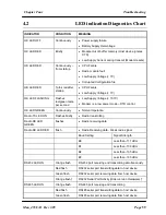
4.2
LED indication Diagnostics Chart
INDICATOR
CONDITION
MEANING
OK LED OFF
Continuously
Power supply failure
Battery Supply Overvoltage
OK LED RED
Briefly
Module Out of buffer memory (Host device ignores
CTS)
Low Supply Current during transmit (Modem resets)
OK LED RED
Continuously
–
from startup
CPU Failure
Radio module fault.
Low Supply Voltage (< 7V)
Corrupted Configuration file
OK LED RED
Turns red after
startup
CPU Failure
Low Supply Voltage (< 7V)
OK LED FLASHING
Flashes
red/green twice
per second
Low Supply Voltage (< 10.7V)
Modem is in low power mode
– DTR control.
OK LED GREEN
Continuously
Normal Operation
Radio TX LED ON
Flashes briefly
Radio transmitting
Radio RX LED
GREEN
flashes
Radio receiving data
Radio RX LED RED
flash
Radio Receiving data - Weak radio signal
Baud Setting
Signal Strength
B0
Less than -111 dBm
B1
Less than -108 dBm
B2
Less than -105 dBm
B3
Less than -100 dBm
RS232 LED ON
Orange flash
RS-232 port receiving and transmitting simultaneously
Red flash
RS232 serial port transmitting data to host device
Green flash
RS232 serial port receiving data from host device
Orange flash
†
RS232 Serial Port Activity (Older version Hardware)
†
RS485 LED ON
Orange flash
RS-485 port receiving and transmitting
Red flash
RS485 serial port transmitting data to host device
Green flash
RS485 serial port receiving data from host device


