


455U-D Radio Modem
User Manual
Page
58
©
Jan 2016
Chapter Four
TROUBLESHOOTING
4.1
Power-up and Normal Operation
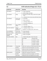
When power is initially connected to the 455U-D module, the module will perform internal
diagnostics to check its functions. The following table details the status of the indicating LEDs
on the front panel under
normal
operating conditions.
LED Indicator
Condition
Meaning
OK
Green
Normal Operation
Off
Power Disconnected or Battery Over-voltage
Red
Low Supply voltage or Internal Module fault
Radio RX
Green flash
Radio receiving data
Red flash
Weak radio signal
Radio TX
Flash
Radio Transmitting
RS232
Yellow flash
†
RS232 Serial Port Activity (Older version Hardware)
†
Orange flash
RS-232 port receiving and transmitting simultaneously
Red flash
RS232 serial port transmitting data to host device
Green flash
RS232 serial port receiving data from host device
RS485
Yellow flash
†
RS485 Serial Port Activity (Older version Hardware)
†
Orange flash
RS-485 port receiving and transmitting
Red flash
RS485 serial port transmitting data to host device
Green flash
RS485 serial port receiving data from host device
DCD
Green
Modem is Online and ready to send data.
Red
Modem is Online but Currently in Command Mode
Off
Communications failure or data connection not established
† Hardware version 1.5 and later has extended LED functionality, providing red & green
indication on the serial LEDs. Earlier hardware support single-color (yellow) serial LEDs.
Check hardware version using ATI5 command.


