


455U-D Radio Modem
User Manual
Page
24
©
Jan 2016
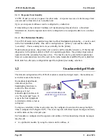
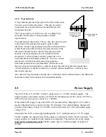
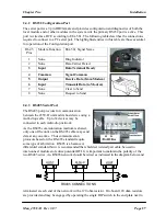
2.2.2 Yagi antennas.
A Yagi antenna provides high gain in the forward direction,
but lower gain in other directions. This may be used to
compensate for coaxial cable loss for installations with
marginal radio path.
The Yagi gain also acts on the receiver, so adding Yagi
antennas at both ends of a link provides a double
improvement.
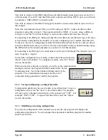
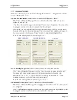
Yagi antennas are directional. That is, they have positive gain
to the front of the antenna, but negative gain in other
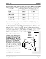
directions. Hence Yagi antennas should be installed with the
central beam horizontal and must be pointed exactly in the
direction of transmission to benefit from the gain of the
antenna. The Yagi antennas may be installed with the
elements in a vertical plane (vertically polarized) or in a
horizontal plane (horizontally polarized). For a two station
installation, with both modules using Yagi antennas,
horizontal polarization is recommended. If there are more
than two stations transmitting to a common station, then the Yagi antennas should have
vertical polarization, and the common (or “central” station should have a collinear (non-
directional) antenna.
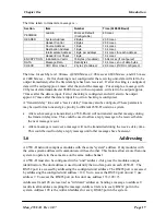
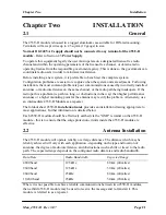
Also note that Yagi antennas normally have a drain hole on the folded element - the drain hole
should be located on the bottom of the installed antenna.
2.3
Power Supply
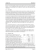
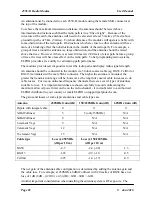
The 455U-D has a 15-28VDC “normal” supply and a 12 - 15VDC alternate supply. The
supply requires a minimum capacity of 24 Watt for the high power radio version (0.5-5W) or
6W for the low radio power version (10 – 500mW).
If the normal 24V supply is used, the 455U will provide battery charging for a 12V sealed
lead-acid backup battery connected to the 12V terminals. The internal battery charger will
provide a float charge voltage of 13.8VDC with current limit set to 0.8A (minimum supply
voltage 15V).
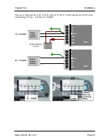
Alternately the 455U can be supplied through the “12V” terminals using a 12-15V supply.
For DC supplies, the negative side of the supply is connected to earth (“Earth” terminal). The
supply negative is connected to the module case internally. The positive side of the supply
must not be connected to earth.
The DC supply may be a floating supply or negatively
earthed.
Directional Antenna
installed with drain
holes down
45
o
Coax feed looped at
connection


