background image

Orange 

White

Yellow 

Orange/black

White/black 

Yellow/black

NC

COM

NO

NC

COM

NO

(Lock signal)

(Unlock signal)

EC002 output

Lock

Unlock

NOT USED-Don’t connect (insulate separately)

+12V(vehicle fused +12V constant)

+12V(vehicle fused +12V constant)

Drivers door

L

UL

NOT USED-Don’t connect (insulate separately)

(+)Door Lock Wire

(+)Door Unlock Wire

central car lock control unit

Door Lock Switch

FACTORY LOCK

SWITCH

LOCK

UNLOCK

+12V

L

UL

Factory Door
Lock Module

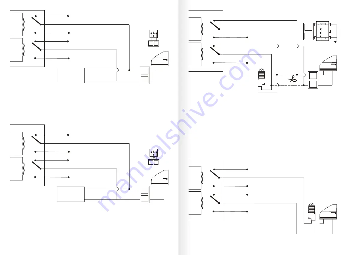
Type B: Negative trigger with three-wire (-) pulse controlling factory lock relays.

Two wires resting open circuit, one pulses ground for lock and the other pulse for unlock.

For this kind of trigger, the vehicle switch will have three wires on it, one wire will test ground all the time. One 
wire will pulse (-) when the switch locks the doors, and the other wire will pulse (-) when the switch unlocks 
the doors. This type of system is difficult to mistake for any other type.

Orange 

White

Yellow 

Orange/black

White/black 

Yellow/black

NC

COM

NO

NC

COM

NO

(Lock signal)

(Unlock signal)

EC002 output

Lock

Unlock

NOT USED-Don’t connect (insulate separately)

Drivers door

L

UL

NOT USED-Don’t connect (insulate separately)

(-)Door Lock Wire

(-)Door Unlock Wire

central car lock control unit

Door Lock Switch

FACTORY LOCK

SWITCH

LOCK

UNLOCK

L

UL

Factory Door
Lock Module

Chasis Ground(-)

Chasis Ground(-)

Type C: Reverse polarity, positive triggered

Motor interrupt central locking:

Two wires resting at ground, one pulse 12V for lock, the other pluses 12V 

for unlock.    

Direct-wired  reversing-polarity  switches.  The  switches  are  wired  directly  to  the  motors.  This  type  of  system 
has no factory relays.

Orange 

White

Yellow 

Orange/black

White/black 

Yellow/black

NC

COM

NO

NC

COM

NO

(Lock signal)

(Unlock signal)

+

12V


(vehicle fused co12V)

+

12V


(vehicle fused co12V)

 Down

up

(+)Door Lock Wire

(+)Door unlock Wire

X

X

L

UL

Drivers door

Door lock switch 
on the front door

EC002 output

Lock

Unlock

L

UL

+12V

Type D: Adding one or more aftermarket actuators. 

For this type of vehicle, there isn’t a motor in the driver’s door( central locking only operates from the driver’s 

door). An extra door actuator is required.

These include central locking systems without an actuator in the driver’s door, but with factory actuators in all 

the other doors. Type D also includes vehicles without power locks, which will have actuators added.

Vehicles without factory power door locks require the installation of one actuator on each door. This require 

mounting the door lock actuator inside the door. Other vehicles may only require one actuator installed in the 

driver’s door if all door locks are operated when the driver’s lock is used.

Orange 

White

Yellow 

Orange/black

White/black 

Yellow/black

NC

COM

NO

NC

COM

NO

(Lock signal)

(Unlock signal)

+

12V

(vehicle fused co12V)

Drivers door

EC002 output

Lock

Unlock

chassis ground

+

12V

(vehicle fused co12V)

chassis ground

-26-

©


EASYGUARD


Electronics

All


right reserved.

-25-

©


EASYGUARD


Electronics

All


right reserved.

Summary of Contents for EC002 Series

Page 1: ...Phone 86 760 22113597 Web www ieasyguard com Email sales ieasyguard com Important This device can improve the vehicle safety level but could not prevent the vehicle from stolen or the occurrence of unexpected accidents EASYGUARD Electronics will not be liable for any resulting from the damage of this product cause by direct or indirect losses Contact us ...

Page 2: ...ergency override 40 21 Power saving car battery low power protection 40 22 Automatic window closing optional 40 23 Vibration alarm optional 41 24 GPS tracker optional 41 25 Parameter time prolong setting 41 42 Technical parameter 42 FAQS of EC002 43 44 Function description Installation guide Safety warning 1 1 Before starting the installation 2 3 2 DIP switch setting on control module 3 3 Deciding...

Page 3: ... high quality digital multi meter before making connections Do not disconnect the battery if the vehicle has an anti theft coded radio If equipped with an air bag avoid disconnecting the battery if possible Many airbag systems will display a diagnostic code through their warning lights after they lose power Disconnecting the battery requires this code to be erased which can require a trip to the c...

Page 4: ...ress down or up the DIP switch you want to re set c Re plug the 6 pin ignition wire harness to re power the device Important Only start installation when you receive all the accessories If there is missing any parts please stop installation immediately and contact your vendor right away for the replacement 2 DIP Switch Setting on Control Module Please set the DIP switch on the control module to fi...

Page 5: ...cargo Mount the 5M PKE antenna in the bumper behind the license plate Pickup without cab Recommend the PKE antenna on position C the PKE antennas should be mounted on the driver and passenger side as the tailgate does not require to be controlled Convertible Mount the 2 9M PKE antenna in front windshield pillar on driver side and the 5M PKE antenna behind the rear seats Note On vehicle with fiberg...

Page 6: ...heat shrink Never twist and tape the wires together without soldering Never use fuse taps as they can damage fuse box terminals 08 EASYGUARD Electronics All right reserved 07 EASYGUARD Electronics All right reserved P1 Apillar near the cab in the car P3 P5 P4 Important All the recommend mount position is for reference only and user can adjust the mount position to get a maximum antenna working ran...

Page 7: ...ee Note 8 or shock sensor see note 9 connect with GWR from bypass module Connect with EC002 ACC or ignition 1 ACC is recommend connect with chassis ground GND You can also use a SPDT relay to generate a GWR wire and wiring method is the same but no need to connect 87a on SPDT relay Wire colors Yellow black The 1st row 10 pin wires Wire usage Turn signal light parking light Turn signal light parkin...

Page 8: ...8 Can be changed to positive by jumper see note 10 18 See note 11 See note 12 See note 15 See note 15 see note 13 14 see note 13 14 1 2 3 4 5 6 trunk motor cut off the trunk wire Output of the trunk connect with 12V wire Purple wire Green wire Green black wire Note 13 Wiring method of negative trigger of the trunk Note 14 Wiring method of Positive trigger of the trunk If the trunk is positive trig...

Page 9: ... DIP switch 2 on alarm control module wait for around 5 minutes d Re plug 6 pin ignition wire harness to re power of the device Then you should able to use dome light supervision function now Some things to remember about mounting the siren Keep it away from heat sources such as radiators exhaust manifolds turbo chargers and heat shields Note 16 Window closer module wire connection with Ec002 If t...

Page 10: ... The outer rubber is detachable Ø10mm Ø56mm Ø 41mm Button thickness is 10mm Ø52mm Ø 41mm 47mm Ø 38mm Ø 27 5mm Ø 27 5mm The ring is detachable P7n style engine start button P4 style engine start button P5 style engine start button Ø 38mm Ø 27 5mm 47mm Ø 27 5mm The ring is detachable 64mm Ø 41mm 47mm Ø 38mm Ø 27 5mm Ø 27 5mm The ring is detachable 16 EASYGUARD Electronics All right reserved 15 EASYG...

Page 11: ...y from the vehicle when use remote engine start function 4 Remote engine cut off Once the vehicle is remote started keep pressing the start button for around 3 seconds will remote cut off the engine Please keep at least 8 meters away from the vehicle when use remote engine cut off function Arm Panic mode Disarm LED indicator Spare key Start button trunk release P LED indicator Disarm Spare key Arm...

Page 12: ...tive function Please follow the following instruction to avoid damage 1 Don t put the remote control in an environment with damp sunshine or high temperature 2 Don t dismantle the remote control The users can t inspect the components inside 3 To avoid strong strike or heavy crash 4 Don t put the remote control together with the metal keys or avoid damage or signal shielding 5 Don t put the remote ...

Page 13: ...ction wire well around the ignition lock header to make sure that the car can be started Please fix the car OEM Programming method Important When you do the programming please remember to keep pressing the programming switch on the control module all the time till you finish the programming on both remote controls Once the vehicle is enter programming status need to finish both key fobs programmin...

Page 14: ... multiplex One wire controls lock and unlock using resistor s Type H Negative multiplex Same as Type G system but uses pulse instead Here is the EC002 series central door lock wire harness principle Orange White Yellow Orange black White black Yellow black NC COM NO NC COM NO Lock Unlock Lock signal Unlock signal Common Normally Open Normally Closed Common Normally Open Normally Closed Lock relay ...

Page 15: ...pt central locking Two wires resting at ground one pulse 12V for lock the other pluses 12V for unlock Direct wired reversing polarity switches The switches are wired directly to the motors This type of system has no factory relays Orange White Yellow Orange black White black Yellow black NC COM NO NC COM NO Lock signal Unlock signal 12V vehicle fused constant 12V 12V vehicle fused constant 12V Dow...

Page 16: ...ry door lock module not used insulate separately X Chassis Ground Factory switch Connection when doors are locked Connection when doors are unlocked not used insulate separately Type G Positive multiplex One wire controls lock and unlock using resistor s Single wire positive central locking Single wire positive lock positive unlock Two potential resistor may require positive trigger Single resisto...

Page 17: ...der must be isolated from the factory door lock system For testing use a calibrated digital multi meter that is set to ohms IMPORTANT To ensure an accurate resistance reading do not touch the resistor or leads during testing 1 Cut the output wire from the door lock switch key cylinder in half 2 Test with the meter from the switch side of the cut door lock switch key cylinder wire to a reliable gro...

Page 18: ...re into 2 parts each end connect with the white yellow wire respectively Method 2 If there is GWR wire connect the G R wire with white wire and connect yellow wire with ground GND Method 3 If there is key sense wire which require either ground or positive wire connect the key sense wire with white wire and connect the yellow wire with ground or 12V respectively W connect with GWR from bypass modul...

Page 19: ...e and once the vehicle is started user keep pressing start button for 3 seconds will cut off the vehicle engine When use remote engine start stop function please keep at least 8 meters away from the vehicle when PKE feature is turn on 2 PKE passive keyless entry Lock Turn off the engine exit the vehicle and close all doors well and walk away from the vehicle for 3 5 meters away with the key fobs t...

Page 20: ...remote engine start function If user want to start the engine with remote control please set with below procedure Un plug the 6 Pin ignition wire harness from the control module Press up DIP switch 5 on control module to set the alarm fit for manual transmission car Re plug the 6 Pin ignition wire harness with the control module Park the vehicle shift the gear selector to Neutral position pull the...

Page 21: ...hen finish input right password When finish input wrong password LED1 red color Turn off Turn off Blinks once to confirm if the input is valid Not blink if the input is invalid Blinks once to confirm if the input is valid Not blink if the input is invalid Turn off Turn off LED2 blue color Blinks slowly Turn off Keep lighting on Keep lighting on Blinks 3 times to confirm then turn off Turn off dire...

Page 22: ... input it again Reminder If you install the touch password keypad please remember to revise the password once you finish the installation 15 Power off memory If the vehicle was cut off power suddenly the vehicle will be automatic back to the previous status when re power 16 Door unlock well warning When the user walk away from the vehicle with remote control but not properly close the door well tu...

Page 23: ...means unlock signal prolong 2 seconds Do not step on foot brake pedal press unlock button 3 times siren beeps 3 times means unlock signal prolong 3 seconds The rest can be done in the same manner The device maximum support press unlock button 8 times and siren beeps 8 times means unlock signal prolong 8 seconds If press unlock button more than 8 times siren not beep and user need to follow with po...

Page 24: ...ual 8 How to do programming Please refer to programing method in the user manual 9 How to wire the 3 color orange yellow white GWR wire Please refer to Note 8 in the user manual 10 How to set the device to valet mode Please refer to the valet mode on off in the user manual 11 When I open the door I heard the control module is sound click sometimes but when I close the door it s normal is this a de...

Page 25: ...ures Reorient or relocate the receiving antenna Increase the separation between the equipment and receiver Connect the equipment into an outlet on a circuit different from that to which the receiver is connected Consult the dealer or an experienced radio TV technician for help To assure continued compliance any changes or modifications not expressly approved by the party Responsible for compliance...

Reviews: