background image

1.Parts and Functions


350


EB+


EB

N

.O


L

K+


LK

-


+

1

2

V


Camera  Lens


Night  View  LED 

Speaker


LCD  Screen


Adjustable  Camera


ID Card Window


RF CARD


1          2          3


3  2    1


Connectiong  Port


Digital  Keypad


4          5          6


7          8          9


Microphone


*       

0          #


128 mm  


With  rainy  cover


2. Terminal Descriptions


SD Card Slot


L1     L2


CN-LK


T/R  -T/R+


3   2   1


Bus


RF CARD


3  2    1


J/KMB  

JP-LK


1          2          3


4          5          6


7          8          9


*       

0          #


•   

+12V:

 12VDC power output.


•   

LK-(GND):

 power ground.


•   

LK+(COM):

 common contact of the Relay .


•    

NO.:

normally  open  contact  of  the  Relay(refer  to 2-wire  technical  guide  for  Lock  

connection detail information).


•   

EB+:

 Exit button connection port.


•   

EB-:

 Exit button connection port.


•   

JP-LK:

 For electronic lock safety type setting(refer to Door Station Lock Connections).


•   

T/R-:

 USB-RS485 communication terminal negative.


•   

T/R+: 

USB-RS485 communication terminal positive.


•   

Bus(

L1,L2

):

 non-polarity bus line.


Summary of Contents for DJ LCD ID

Page 1: ...Door Stat ion User Manual RF CARD 1 2 3 4 5 6 7 8 9 0 DJ LCD ID...

Page 2: ...RD 3 2 1 J KMB JP LK 1 2 3 4 5 6 7 8 9 0 12V 12VDC power output LK GND power ground LK COM common contact of the Relay NO normally open contact of the Relay refer to 2 wire technical guide for Lock co...

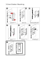
Page 3: ...ainy cover after mounted 3 Camera angle Adjust the camera angle and attach the metal to the panel and wire correctly 4 Attach screws to fix the metal box 5 Attach the unit to the rainy cover correctly...

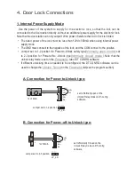
Page 4: ...ition for Power to Unlock safety type Normally open mode set to 2 3 position for Power off to Unlock type Normally closed mode Note that the unlock relay mode is set on the Parameter tab of DT CONFIG...

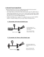
Page 5: ...Parameter tab of DT CONFIG software If different unlocking time is needed to be configured please use the DT CONFIG software to change the setting on the Parameter tab see the program section C Conne...

Page 6: ...S t a t e 0 Re d i a l R F C A R D 1 2 3 1 To o l s 4 5 6 7 8 9 0 9 0 0 8 2 E x i t s Please Input Password When Door Station is in standby press key input 9008 then input the Admin Code 66666666 by...

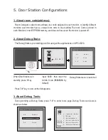
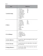
Page 7: ...8 4 Unlock Code 1111 5 Display Mode 6 Clock 7 Setup Code 8 About 9 Default 3 Card Manage 1 Add Card 2 Delete By Card 3 Delete By M code 4 Cards Information 5 Format 4 Online Monitors To search the onl...

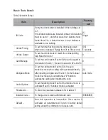
Page 8: ...ocation If set to 0 the card is saved in door station If set to 1 the card is saved in DPA D2 IPC 0 Doorplate Mode To set the calling mode If set to 0 it s the auto mode that means the calling will be...

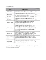
Page 9: ...te can open the door at the same time If set to 0 unlock function is disabled Set to 1 unlock is enable Set to 2 unlock is enable and close at once Set to 3 unlock is enable and close in 5s 1 Ring Num...

Page 10: ...e format is MM DD YY Time format if set to 0 time format is 24 hour standard If set to 1 time format is12 hour standard Setup Code To change the Program Code 88888888 About 1 Hardware version To show...

Page 11: ...page to call the desired flat Residents can open the door by using their unique Unlock Code four digit PIN code If the door station is in standby mode press key then input the four digit unlock to ope...

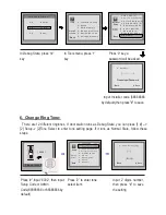
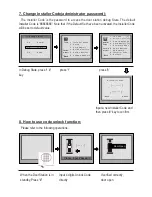
Page 12: ...9 D e f a u l t Please Input Password Back Save Input Installer code 66666666 by default then press to save 6 Change Ring Tone There are 12 different ringtones If door station runs as Debug State you...

Page 13: ...o l s 3 C a r d M e m o r y 5 D o o r p l a t e M o d e Press1 9 6 A u d i o O p t i o n s Pres NO 4 O n l i n e M o n i t o r s to select 7 P a ra m e t e r s 2 E x i t s to select Back 5 O n l i n e...

Page 14: ...ss to update 10 User Card Management This section explains how to configure the key fob function on DPC D218 The key fob is used to open the lock Total 1000 key fobs can be registered with one door st...

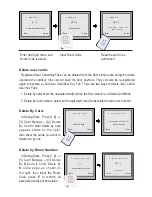
Page 15: ...he unwanted card s when the Door station is in Delete Card Mode 2 Delete by room number delete all the registered User Cards related to that room number Delete By Card In Debug State Press 1 3 Card Ma...

Page 16: ...lease Input Password Back Save 11 Change Door Station Language It s convenient to change the user interface for DPC D218 Just put the config files to the SD card and by means of the digital keypad of...

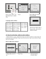
Page 17: ...lish 8113 Russian 8114 Slovakia 8115 Hungary 8116 Czech When the door station output a long sound DI that means UI updating is finished 12 Search online door stations and monitors Online Search is a v...

Page 18: ...st function on the screen and customer can do the calling operation through the digital keypad guided by Namelist on the screen 2 types of namelist can be shown on the screen DT Config namelist and Si...

Page 19: ...r supply DC24V Powered by DPA D2A Camera Lens 1 4 ACS 4T image sensor with DSP processor Power consumption Standby 3W Working status 9W Screen 3 5 inch TFT Resolution 320 R G B X240 pixels Video signa...

Reviews: