


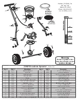


Pt. #53192
5
10
1
5
3
0
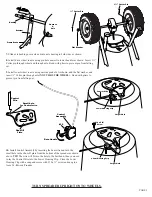
Inser
t Contr
ol R
od
into the Piv
ot Br
ac
ket
Attac
h 1/4-20 R
e
gular
He
x Nuts a
t these points.
Notice the position
of
the double ben
d point.
It must be a
t this loca
tion
30
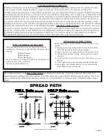
Br
oadcast Setting Matrix
Calibration T
echniques
Shut-Of
f
Full
y Open
Tighten Scr
ew
Slide Outer Contr
ol W
ir
e
to Calibr
ate
Cable T
ype Adjustment
Loosen/tighten screw on cable clamp then
slide outer cable in/out for calibration
Fig 2
Dr
op holes shown fully open.
How to ensur
e your spr
eader is pr
operly calibrated
Make sure the drop holes in the bottom of the hopper are fully open when the Rate Control handle is on
#30
. If not, please
adjust control cable or control rod to allow for a full open hopper position at
#30
.
Rod T
ype Adjustment
1.
Open the shut-off so that the drop holes are completely open as illustrated to the right.
2.
Review the Control Lever position - if it is set so that the forward edge is at #30, you are calibrated. If not,
you
need to adjust the control rod at the pivot bracket shown in
Fig 1
.
A.
If your shut-off is not able to open fully as in step #1. Loosen the top nut a few turns, then loosen the lower nut
so that it allows you to push the shut-off open fully
. Next tighten each nut so that they contact the pivot bracket
without moving it, and then carefully tighten each nut fully so they do not loosen during use. Recheck adjustment
as outlined in #1 above.
B.
If your shut-off is able to open fully as in step #1, but the Control Lever is not at #30. Loosen the top nut a few
turns, then loosen the lower nut so that it allows you to push the Control Lever to #30. Next tighten each nut so
that they contact the pivot bracket without moving it. Carefully tighten each nut fully so they do not loosen during
use. Recheck adjust as outlined in #1 above.
Cable T
ype Adjustment
1.
Open the Control Lever so that the shut-off and drop holes are completely open as illustrated above right.
2.
Review the Control Lever position so that the indicator is pointed to #30, if it is your calibration is correct. If not you
need to adjust the control cable at the cable clamp on the underside of the hopper as shown in
Fig 2
.
A.
If your shut-off is not able to open fully as in step #1. Loosen the cable clamp screw slightly so that you can slide
the outer cable out so that the shut-off is fully open. Next tighten the cable clamp screw securely
. Recheck
adjustment as outlined in #1 above.
B.
If your shut-off is able to open fully as in step #1, but the Control Lever is not at #30. Loosen the cable clamp screw
slightly so that you can slide the outer cable in so that the Control Lever opens to #30. Next tighten the cable clamp
screw securely
. Recheck adjustment as outlined in #1 above.
If you have any questions regarding the operation or assembly of your spreader please call us at 800-294-0671 or
574-848-7491 Monday - Friday 9:00am - 4:00pm Eastern.
Accessories and Repair Parts
are also available at these
numbers.
Fig 1