


¼-20 x 1½”
Hex Bolts
¼-20 Lock
Nuts
¼-20 x 1¾”
Carriage Bolt
¼-20 Hex
Nut
Upper Handle
Assembly
Draw Bars
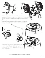
12.
Install Control Assembly onto Upper Handle by sliding the Control Assembly over
Upper Handle shaft then securing with ¼-20 x 1¾” Carriage Bolt and ¼-20 Hex Nut.
TIGHTEN BOLTS AND NUTS NOW.
m
akE
surE
to
Position
thE
c
ontrol
a
ssEmBly
w
irE
above
thE
d
raw
B
ar
and
u
PPEr
h
andlE
assEmBly
as
shown
.
13. CALIBRATION - THIS STEP ENSURES THAT YOUR 2100P IS PROPERLY
ADJUSTED TO GIVE YOU A CORRECT STARTING POINT TO APPLY
MATERIALS AT THE CORRECT SETTING. NOW TURN THE SPREADER
OVER ON TO THE HOPPER.
With the spreader resting on it’s hopper push the
Control Handle forward to #30, then push the shut-off plate forward until the shut-off
and the drop holes are fully open. Now tighten the #10 Screw on the Lower Housing
Clip firmly. Check to confirm calibration by closing the Control Handle, and reopening
to #30 and confirm that the drop holes are fully open.
14.
Insert agitator to pinion shaft on inside of hopper.
Note:
the position of flat side of the agitator. This pin
should be installed as shown.
PAGE 4
11.
Install Upper Handle between Draw Bars. Insert ¼-20 x 1½” bolts through Draw Bar
and Upper Handle and secure with ¼-20 Lock Nuts.
TIGHTEN BOLTS AND NUTS
NOW.
Lower Housing Clip
Control Wire
Shut-Off
#10 Screw
Larger Hole
Open to #30
to calibrate