Earthcore Industries
Isokern Maximus Linear Series See-Thru Gas Fireplace
02/2021
38
Chimney Fan – Horizontal Termination Installation
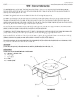
5.
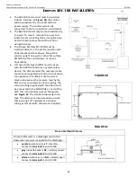
To ease installation, detach the fan base by
removing the bolts holding the hinges together.
Center the fan base over the outlet and bolt the
base onto the wall with the hinges pointing
upwards. (
Figure 32
)
6.
After mounting the base securely, attach the fan
motor housing by reassembling the fan hinges.
Seal with silicone all around the fiber mat to
prevent rain from entering the flue.
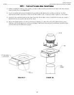
7.
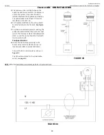
In order to achieve optimal performance and
energy consumption for the RS Fan, the duct must
be installed as shown below and the distances
observed. From the last elbow to the termination
point the distance must be 4 times the diameter of
the flue. For example, if you using 12in flue (12 X 4
= 48in). The distance from the last elbow to the fan
termination point should be 48 inches. (
Figure 33
)
8.
A venting system that terminates in the sidewall of
a structure shall terminate at least 3 ft (0.9 m)
above any air inlet to the structure that is within
10 ft (3 m) of the termination point.
Exception:
This requirement shall not apply to the
separation distance between the circulating air inlet
and the vent discharge of a listed outdoor appliance.
NOTE:
The flue gas outlet of this appliance shall
terminate at least 4 ft (1.2 m) below, 4 ft (1.2 m)
horizontally from, or 1 ft (0.3 m) above any door,
window, or gravity air inlet of the structure. The outlet
also shall terminate at least 1 ft (0.3 m) above grade.
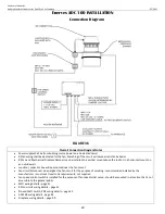
9.
ADC100
must be interlocked with the appliance(s).
The safety system will utilize a Proven Draft Switch,
PDS. The PDS device must be interlocked with the
gas appliance, so it shuts down in case of
insufficient draft, fan failure or power failure.
Please refer to the PDS Installation Manual if this
control is used.
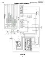
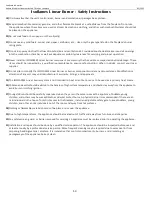
10.
The
Figure 34
shows the location of the probe
for the PDS. Location is important to make sure
there is enough pressure or draft available or the
switch to work. PDS location to be at 3’ from last
elbow before termination of vent system.
IMPORTANT:
Framing and sheathing at horizontal termination
shall require non-combustible material within the 18” clearance
zone as measured from outer diameter of MFD collar.
FIGURE 32
FIGURE 33
FIGURE 34

