Earthcore Industries
Isokern Maximus Linear Series See-Thru Gas Fireplace
02/2021
34
RS Chimney Fan - General Information
The RS Chimney Fan is a chimney top mounted ventilator that is designed to provide large flue gas volume capacities. It is
designed and intended for use with residential gas or oil-fired central space heating systems, for volume water heating or
for combination space heating/volume water heating. It is also suitable for use with gas-fired fireplaces.
This product is developed to prevent draft problems from occurring by creating a mechanical draft in venting systems and
thereby also increasing the capacity and efficiency of a venting system.
The use of the RS Chimney Fan is not restricted to any type of chimney, because the fan creates a negative pressure (below
atmospheric) in the chimney or vent.
CODE COMPLIANCE
Installations must conform to requirements of the authority having jurisdiction. Where required by the authority having
jurisdiction, the installation must also conform to the Standard for Draft Equipment and The National Fuel Gas Code, ANSI
Z223.1/NFPA 54.
All electrical wiring must be in accordance with the requirements of authority having jurisdiction or, in the absence of such
requirements, with the National Electrical Code, NFPA70.
LISTINGS
The Model RS is tested and listed to UL Standard 378, Standard for Draft Equipment. The fan is manufactured at an ISO9001
certified plant and bears the European CE compliance label.
The chimney fan must be interlocked with the connected appliance(s) to ensure proper combustions and to avoid flue gas
spillage.
WARRANTY
ENERVEX products are warranted for a period of two (2) years following the date of invoice. Replacement or repair will be at
ENERVEX’s discretion, provided factory inspection shows a defect in material or workmanship.
Complete warranty conditions are available from ENERVEX.
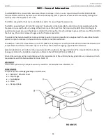
1. Junction Box
8. Locking Nut
2. Conduit/ Cord
9. Inlet
3. Motor
10. Axial Vane
4. Motor Housing
11. Hinges
5. Motor Plate
12. Capacitor
6. Bird Screen
(inside Junction Box)
7. Base Plate
FIGURE 26


