4810 Clover Road • Greensboro, NC 27450 • 1-800-336-2776 • www.eagleequip.com • © Eagle Equipment 2018.01 • page 16
3. INFLATING THE TIRE CONT.
NOTE:
1. When inflating tire or locking rim, air pressure must not exceed 3.5bar (50psi). Failure to comply my
result in injury or death.
2. If higher air pressure is required to inflate tire, take tire off from tire changer, and put it
into inflating cage, then start inflating. DO NOT inflate the tire with pressure higher than that
recommended by tire manufacturer.
3. Operators should be trained professionals only. Untrained personnel should not operate this machine.
4. MOVING THE MACHINE
A forklift is required to move the tire changer. Cut off air supply and electricity supply, lift base a little
bit, insert lift fork into bottom base, move tire changer to new position, then secure tightly.
NOTE: Installation position of tire changer must comply with safety regulation.
5. MAINTENANCE
CAUTION:
Maintenance should be preformed by professionals. To prolong the machine’s life, maintain
the machine timely according to the manual. Otherwise, it will impact the reliability of the machine
or cause injury to operator and others nearby. Before performing any maintenance, disconnect the
tire changer from the electric power supply and pneumatic power supply, and tread rotation pedal
for 3-4 times to evacuate all compressed air from the machine. Damaged parts must be replaced by
professional persons with the spare parts provided by Eagle Equipment.
- Clean the machine once every day after work. Clean the dirt on the tire installation base with diesel
oil once per week and lubricate the slides and shafts.
- Following maintenance must be done at least once per month:
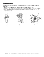
Check oil level in Oil Fog Maker, please be filled with SAE30# oil if need.
Unscrew with hex wrench (E). Based on connection of compressed air, first to tread Rotation Pedal 5-6
times, and then check whether oil in Oil Fog Maker drops down a drip of oil. For continuous
operation, tread twice every time, drop down a drip of oil, and otherwise adjust the screw (D) that
controlled oil enters with minus screwdriver (Figure 25).
NOTE: In the event of tire installation base loses power, check to see if the belt is tight as follow steps:
Remove the left side cover by unscrewing the screws; adjust two screws located on the motor support,
keep a suitable distance between motor support and motor base; tight the screws for the belt tension
(Figure 26).
CAUTION:
Disconnect the machine from electric power supply and pneumatic power supply.

