background image

4810 Clover Road • Greensboro, NC 27450 • 1-800-336-2776 • www.eagleequip.com • © Eagle Equipment 2018.01  • page 15

2. ASSIST ARM APPLICATION CONT.     

C. Install the tire
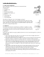
1.  Lubricate tire and rim edge with lubricant to avoid tire damage. Adjust height of demount/mount  
 

head and make tire bottom bead upon rear of demount/mount head and below front of mounting/ 


demounting head. Rotate tire installation base to mount bottom bead.

2.  Make the tire top bead upon rear of demount/mount head and below front of demount/mount  
 

head, clip the tire pressing head (up) on the rim. Move the auxiliary tire pressing head (up) near  


the mounting/demounting head (distance 3-4cm), lower the tire pressing head (up) to press down  


the tire 3-5cm below mounting/demounting head, rotate turntable, tire pressing head (up) will  


follow in synchrony as to rotate and press the tire down in tire rim.

ATTENTION:

1.  To keep the assist arm and mounting/demounting head from colliding, do not excessively rotate  
 

the installing base while using assist arm.

2.  Make sure the tire pressing head (up) never press on the tire rim, the friction between them will  
 

damage the tire rim. Keep your hands away from the tire pressing head (up).

3. INFLATING THE TIRE     

WARNING:

 All operations in this chapter refer to manual of machine equipped 

with inflating gun.
The inflating operation can be very dangerous. Comply with instruction. When 
inflating, if the tire or rim become damaged, it will become very dangerous to 
continue inflation. The possible burst force of a tire goes upward and outward, 
and may cause injury or death of the operator or the people around.
Tire burst may be caused by following:
1.  The wheel rim and the tire are not of the same size.
2.  The tire or the wheel rim is damaged.
3.  The pressure of tire inflation is over the maximum pressure recommended by manufacturer.
4.  The operator fails to comply with the safety regulation.
Please operate as follows:
1.  Remove the valve cap from the valve stem.
2.  Check to make sure the air nozzle is pressed down completely over the threads of the valve stem.
3.  Check to make sure that the tire and the wheel rim are the same size.
4.  Lubricating both the tire bead and the wheel rim, additional lubrication is required if needed.
5.  Inflate the tire with break, while inflating, check the pressure listed on the pressure gauge, also  
 

check whether the bead is fixed or not. Repeat operation above until the bead is secured; you need  


take special steps when inflating convex rim or double convex rim (Figure 24).

6.  Continue inflating and check the air pressure frequently until to reach the required pressure.

Figure 24

Summary of Contents for ETC-2800A

Page 1: ...er Road Greensboro NC 27450 1 800 336 2776 www eagleequip com Eagle Equipment 2018 01 ETC 2800A Instruction Maintenance Manual Center Post Tire Changer with Assist Arm ETC 2800A READ THIS MANUAL BEFOR...

Page 2: ...5 Shipping and Damage Claims 5 Introduction 6 Unpacking 7 Workplace Requirements 7 Important Safety Instructions 8 Overview 9 Specifications 9 Position and Installation 10 Electricity and Pneumatic C...

Page 3: ...and accepted by Eagle Equipment referred to herein as Eagle Risk of Loss Freight Shipping All shipments are FOB the Eagle warehouse which means that ownerships of these goods transfers to the customer...

Page 4: ...is warranted to be free of defects in material and or workmanship for a period not exceeding one year Eagle will replace parts only under this warranty if in Eagle s view there is a defect in materia...

Page 5: ...product In the event the part is determined to not be defective it will be subject to a minimum restocking fee of 20 and the return freight Credit for warranty returns to third party vendors will be s...

Page 6: ...d However safety relies on proper training and thoughtful use on the part of the operator DO NOT operate or repair this equipment without reading this manual and the important safety instructions show...

Page 7: ...quipment and contains smaller components 4 Remove the equipment from the package Literature such as the installation manual warranty card and serial number plate is included inside this box Shipments...

Page 8: ...pment 8 DANGER Disconnect power at the receptacle before performing any electrical repairs Secure plug so that it cannot be accidentally plugged in during service 9 WARNING Risk of explosion This equi...

Page 9: ...ctions Eagle Equipment is not liable for any injury to persons or damage to things caused by improper use of this machine Read the manual carefully before operating the equipment to ensure normal and...

Page 10: ...B by using the nut A through the bolt located on the machine body B If the column becomes loose tighten it immediately Otherwise this may damage the tire 3 Attach the tire lifting device on the side o...

Page 11: ...pedal 1 Tire installation base 17 rotates in a clockwise direction lift Rotation Pedal 1 Tire installation base 17 rotates in an counter clockwise direction 2 Tread bead breaker pedal 3 bead breaker...

Page 12: ...y rotating rod of tire installation base which should be alignment with the fixing hole of tire rim Input the tread shaft positioning the tire with the appropriate cone and then secure the tire with t...

Page 13: ...it is not necessary to loosen and lock vertical arm Only put tire on rim move swing arm to position when demounting tire put one side of tire bottom bead upon rear of demount mount head and the other...

Page 14: ...per operation instruction in user s manual fixing the tire on the tire installation base B Demount tire 1 Press tire with right pressing roller C G to a position 3cm lower than rim edge lubricate tire...

Page 15: ...RNING All operations in this chapter refer to manual of machine equipped with inflating gun The inflating operation can be very dangerous Comply with instruction When inflating if the tire or rim beco...

Page 16: ...by Before performing any maintenance disconnect the tire changer from the electric power supply and pneumatic power supply and tread rotation pedal for 3 4 times to evacuate all compressed air from th...

Page 17: ...ker shovel operate as follows to keep their valves clean 1 Remove the left side cover of the machine body by unscrewing the two screws 2 Loosen the valve mufflers A which belong to Jaws open and close...

Page 18: ...on the air network The clamping cylinder doesn t work Replace the cylinder piston The jaws are worn Replace the jaws Broken washers of the chuck cylinder Replace the washers cylinder The mounting head...

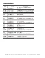
Page 19: ...Bolt M6 10 5 B 040 061412 1 Flat Washer 6 14 1 2 6 B 014 080251 0 Outer Hex Bolt M8x25 7 B 010 080201 0 Hex Socket Head Bolt M8 20 8 B 040 061412 1 Flat Washer 6 14 1 2 200 9 C 000 001020 0 Rubber Foo...

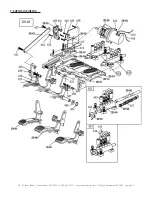
Page 20: ...4810 Clover Road Greensboro NC 27450 1 800 336 2776 www eagleequip com Eagle Equipment 2018 01 page 20 7 EXPLOSIVE VIEW 2...

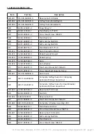
Page 21: ...Barrel 115 B 010 060201 0 Hex Socket Head Bolt M6x20 116 C 298 480000 0 Locking Plate Cap 119 B 010 100301 0 Hex Socket Head Bolt M10 30 228 120 C 200 490000 0 Vertical Arm Cap 228 121 C 200 390000 0...

Page 22: ...Locking Cylinder Cover 60 221 187 S 000 052200 0 O Seal 52 2 188 CX 098 030000 0 Pressing Arm Pin Right 189 B 001 160001 1 Self Locking Nut M16 1 5 221 198 C 221 400000 0 Hex Locking Board Spring 2093...

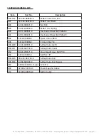
Page 23: ...20X2 65 200 310 C 200 050100 0 Bead Breaker Cylinder Piston Rod 200 315 CX 200 070000 0 Bead Breaker Shovel Assembly 316 B 010 120901 0 Hex Socket Head Bolt M12 90 317 B 004 160001 1 Self Locking Nut...

Page 24: ...e 351 S 012 010808 0 Union 1 8 8 352 C 098 600200 0 Bead Breaker Cylinder Exhaust Valve Cover 353 C 098 600400 0 Seal Washer 354 C 098 600300 0 Bidirectional Seal 355 C 098 600100 0 Bead Breaker Cylin...

Page 25: ...4810 Clover Road Greensboro NC 27450 1 800 336 2776 www eagleequip com Eagle Equipment 2018 01 page 25 7 EXPLOSIVE VIEW 4...

Page 26: ...al Spring 200 415 C 200 061500 0 Cam 200 416 C 200 810000 0 Cam Washer 417 B 010 060201 0 Hex Socket Head Bolt M6 20 420 B 019 290121 0 Cross Head Self Tapping Screw 200 421 CX 200 060500 0 Cam Cover...

Page 27: ...Head Bolt M8 50 441 B 010 080201 0 Hex Socket Head Bolt M8 20 442 S 012 010808 0 Quick Union 1 8 8 445 S 016 010808 2 T Union1 8 2 8 200 449 C 200 060901 0 5 Way Valve Left 200 451 C 200 061100 0 5 Wa...

Page 28: ...Gear Shaft 200 510 C 200 320100 0 Worm Gear 200 511 CZ 200 320600 0 Worm Gear Shaft Spacer 512 B 014 100551 0 Outer Hex Bolt M10 55 513 B 050 100000 0 Spring Washer 10 200 514 B 060 006020 0 Pin 6X20...

Page 29: ...t A 28 605 B 014 080651 0 Outer Hex Bolt M8x65 606 B 040 083030 1 Flat Washer 8X30x3 607 80 S 063 008000 0 Capacitor 80 F 110V 607 50 S 063 005000 0 Capacitor 50 F 220V 608 B 040 102020 1 Flat Washer...

Page 30: ...n Indicator 702 S 035 014150 1 Rubber Connection Hose 703 S 025 104008 0 Notch Nut 704 S 011 010414 1 Straight Union 1 4 1 4 705 B 040 132420 1 Flat Washer 13 706 S 030 010400 2 Pressure Adjust Valve...

Page 31: ...Cushion 924 CX 238 130300 0 Retaining Ring Up 238 925 CX 238 131100 0 Thread Shaft 238 926 CX 238 131000 0 Connection Pin 238 927 CX 238 130200 0 Auxiliary Rotating Rod 238 928 C 238 130400 0 Outer S...

Page 32: ...e Down Support LD09 B 014 121101 0 Outer Hex Bolt M12 110 LD10 CA 005 000001 D Complete Rise Fall Cylinder LD11 CX 0LD 010500 0 Support Rod Item Part No Description LD12 C 0LD 010406 0 Connection Bolt...

Page 33: ...001 1 Nut Silver M4 F9815 S 030 010818 0 Raise Fall Control Valve F9816 S 023 010801 6 Muffler Brass F9817 S 012 010406 0 L Union 1 4 6 F9814 B 004 040001 1 Nut Silver M4 F9815 S 030 010818 0 Raise Fa...

Page 34: ...4810 Clover Road Greensboro NC 27450 1 800 336 2776 www eagleequip com Eagle Equipment 2018 01 page 34 7 EXPLOSIVE VIEW 10...

Page 35: ...arm bottom plate F5025 CX 005 030000 B Tire pressing arm 005B F5011 Flat washer 12 F5026 B 001 160001 0 Self lock nut M16 F5012 CX 099 040101 0 Column F5027 CX 005 050000 B Tire pressing arm pin F5013...

Page 36: ...4810 Clover Road Greensboro NC 27450 1 800 336 2776 www eagleequip com Eagle Equipment 2018 01 page 36 8 CIRCUIT DIAGRAM...

Page 37: ...4810 Clover Road Greensboro NC 27450 1 800 336 2776 www eagleequip com Eagle Equipment 2018 01 page 37 9 PNEUMATIC DRAWING...

Page 38: ...ality equipment at competitive prices for 60 years We carry a full line of automotive lifts two post lifts four post lifts alignment lifts scissor lifts low rise and mid rise lifts as well as models o...

Page 39: ...4810 Clover Road Greensboro NC 27450 1 800 336 2776 www eagleequip com Eagle Equipment 2018 01 page 39 NOTES...

Page 40: ...4810 Clover Road Greensboro NC 27450 1 800 336 2776 www eagleequip com Eagle Equipment 2018 01 page 40 4810 Clover Road Greensboro NC 27450 1 800 336 2776 www eagleequip com Eagle Equipment 2018 01...

Reviews: