background image

Installation, Operation and Parts Manual 

EE-6214EKZ


12 

INSTALLATION INSTRUCTIONS 

4.1 Preparations before installation 

4.1.1 Space requirements.   

Indoor installation only. 

Refer to 3.4 for the dimensions of the lift. There must also be a clearance of at least 1 meter between the 

lifting platform and fixed elements (e.g. wall) in all lifting positions. There must be sufficient space for driving vehicles on and off. 


4.1.2 Foundations and connections   

The user must have the following work performed before erecting the lift.   


Construction  of  the  foundation  following  consultation  with  the  manufacturer’s  customer  service  or  an  authorized  service  agent. 

Routing  of  the  wiring  to  the  installation  location.  The  user  must  provide  fuse  protection  for  the  connection. 

Electrical  system 

connection must be done by a qualified electrician.

 Requirements for power supply cable of the installation site: at least 2.5mm

wire 

core for 3Ph power and 4.0mm

wire core for 1Ph power.


Refer also to the corresponding information on the name plate and in the operation instructions. Before doing electrical connection, 

make sure the lift is electrically adapt to the local power supply.   


Foundations preparations (see Annex 1, floor plan) 

To ensure stability and safety under load, the lift shall be installed with the base frame being in direct and firm contact with the concrete 

foundation. Don't attempt to fix the base frame directly onto floor with ceramic and other decorated surfaces otherwise you put the lift 

into a very dangerous situation. 

C25 concrete foundation with a minimum thickness of 200mm.   

Surface under base of the post: Horizontal and even (Gradients max. 0.5 %). 

Newly built concrete ground must be older than 20days. 

4.1.4 Tools and equipment needed for installation   

Tool name 

Specification 

Quantity needed 

Electrical drill 

With D18 drill bit. 

Open spanner 

D17-19mm 

Adjustable spanner 

bigger than D30mm 

Cross socket screw driver   

PH2 

Quick spanner handle adapter/ Ratchet 

REB-310 

Socket spanner   

D24mm 

Levelling device 

1mm accuracy 

Hammer   

10 pounds   

Truck lift   

Capacity more than1000 kg 

Lifting string   

Capacity, 1000 kg 

Torque spanner   

MD400 


Summary of Contents for EE-6214EKZ

Page 1: ...r Two Post Lift Electrical Release Lifting Capacity 4000KG Installation Operation and Parts Manual Distributed by Please read this entire manual carefully and completely before installation or operati...

Page 2: ...er domestic legislation The reproduction or disclosure of instructions or an extract thereof is prohibited and offenders are liable to prosecution EAE reserves the right or initiates criminal proceedi...

Page 3: ...IPTIONS 9 3 1 General descriptions 9 3 2 Construction of the lift 9 3 3 Technical data 9 3 4 Dimensions 10 3 5 Safety devices descriptions 11 INSTALLATION INSTRUCTIONS 12 4 1 Preparations before insta...

Page 4: ...on chosen satisfies the requirements The user bears special responsibility if employees of the company are appointed as experts or qualified persons 1 2 1 Scope of checking Regular checking essentiall...

Page 5: ...es with its maximum weight within the lifting capacity 1 3 10 Always insure the safety locks are engaged before any attempt to work near or under the vehicle Never remove safety related components fro...

Page 6: ...clearly depicted on the lift to ensure that the operator is aware of and avoid the dangers of using the lift in an incorrect manner The labels must be kept clean and they have to be replaced if detac...

Page 7: ...ury danger of crushing In the event of excessive vehicle weight incorrect mounting of the vehicle or on removing heavy object there is a risk of the vehicle falling off or tipping up Safety measures T...

Page 8: ...never stack to more than 2 meters in height never make stacks of single packs Always stack pairs of packs in a cross pattern so that the base is bigger and the resulting stack is more stable Once the...

Page 9: ...ushes upwards its piston The cylinder piston drives to raise the carriage and swing arms It is equipped with mechanical safety locking unit which ensures no risks of slipping off in case of hydraulic...

Page 10: ...Installation Operation and Parts Manual EE 6214EKZ 10 3 4 Dimensions...

Page 11: ...nt at maximum safety height 2 Mechanical locking unit Catch the carriages in case of hydraulic failure 3 Steel cable Ensure the synchronization for both carriages 4 Arm locking unit Ensure the lifting...

Page 12: ...to the corresponding information on the name plate and in the operation instructions Before doing electrical connection make sure the lift is electrically adapt to the local power supply Foundations p...

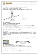
Page 13: ...Please pay special attention not to let the post fall down for it may cause casualty or bring damages to the accessories fixed in the post Step 3 When the first post has been taken away place somethin...

Page 14: ...o check the vertical alignment of the posts If necessary place equalizing plates under the base plates 6 Impact and drive anchoring bolt into hole until nut and washer contact base Tighten the nuts wi...

Page 15: ...hoses NO 4 and 5 in the below Fig to the T connector in the main post Don t let any solid substance go into the hydraulic line Ensure the connectors are screwed tight against leakage 1 Composite conn...

Page 16: ...ectricians 1 Fix the operation unit onto the main post 2 Fix max height limit switch onto the inside surface of the main post and connect its wire with the corresponding wire comes from the control bo...

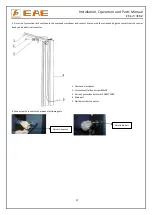
Page 17: ...onnect its wire with the corresponding wire comes from the control box by quick electrical connector 4 Connect quick connectors between electromagnets 1 Overhead crossbeam 2 Cross socket flat head scr...

Page 18: ...Installation Operation and Parts Manual EE 6214EKZ 18 5 Connect electrical wires referring to the following wire connection diagram Check that the supply voltage is adapted to the voltage of the lift...

Page 19: ...a few cycles before loading vehicle on lift This step is of particular importance for it can check if the oil hoses are well connected The connection is qualified when there is no abnormal sound or le...

Page 20: ...o carriages 5mm 6 Mechanical catch unit is robust and synchronized when running with rated load 7 If the control button works as hold to run 8 If limit switches work well 9 If grounding wire is connec...

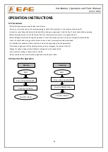
Page 21: ...ration run the lift without load for a complete cycle to ensure it is in good condition Before lifting the vehicle and during all operations on the vehicle make sure that it is properly stopped by the...

Page 22: ...nless you are assured that no damage will occur Raise the lift Make sure vehicle is neither front nor rear heavy and center of balance should be midway between adapters and centered over t he lift 1 P...

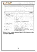
Page 23: ...an or make adjustment Damaged gear pump Replace it Too low oil level Add oil The hose connection is loose Tighten it The cushion valve is not well screwed up or jammed Clean or make adjustment Carriag...

Page 24: ...o ensure no leakage before using the lift Every day 4 Control buttons Check if control buttons work as hold to run and check if they work as the function indicated Every day 5 Mechanical safety lockin...

Page 25: ...irclip is in its original position Every 3 months 14 Expansion bolts Check with torque spanner Torque 80 100Nm Every 3 months Whole Lift Running the lift for several cycles with and without rated load...

Page 26: ...ast 1 meter between the lifting platform and fixed elements e g wall in all lifting positions There must be sufficient space for driving vehicles on and off C25 concrete base with a minimum thickness...

Page 27: ...Installation Operation and Parts Manual EE 6214EKZ 27 Annex 2 Electrical schemes and parts list...

Page 28: ...Installation Operation and Parts Manual EE 6214EKZ 28...

Page 29: ...Installation Operation and Parts Manual EE 6214EKZ 29...

Page 30: ...400V230V 24V QF 320802001 Circuit breaker 1Ph 2 2kW 1 320803003 Circuit breaker 3Ph 2 2kW 320801003 Circuit breaker 3Ph 3 5kW QF1 320803003 Circuit breaker 1 QF2 320803006 Circuit breaker 1 KM 3209010...

Page 31: ...aulic schemes and parts list 1 oil tank 8 overflow valve 2 oil filter 9 single way valve 3 gear pump 10 solenoid unloading valve 4 coupling 11 flow control valve 5 aluminium motor 12 tank cover 6 hydr...

Page 32: ...1PH 50HZ 2P 1 320201002 AC motor 230V 2 2KW 1PH 50HZ 2P 1 320201003 AC motor 240V 2 2KW 1PH 50HZ 2P 1 320201004 AC motor 380V 2 2KW 3PH 50HZ 2P 1 320201005 AC motor 400V 2 2KW 3PH 50HZ 2P 1 320201006...

Page 33: ...5F 1 12 330201008 Gear pump 3 5kW CBK F242 1 13 204101005 Washer M8 4 14 204201013 Spring washer M8 2 15 202109072 Hex socket cylinder head screw with spring washer M8 85 2 16 330502013 Lid of oil ta...

Page 34: ...4 204101009 Class C flat washer M16 4 5 201201008 Expansion bolt M18x200 10 6 625000013 Oil cylinder YG5060 38 1800 2 7 624008080 Oil hose L 8650mm 1 8 410170101B Cylinder fixation ring 6264 A24 B1 2...

Page 35: ...de Description Specification Qty 65 202109085 Hex socket cylinder head screw M12 30 8 66 204101007 Flat washer M12 8 67 204201006 Spring washer M12 8 68 614035031 Crossbeam 6215EKZ V2 A6 B1 1 69 42006...

Page 36: ...81 204101006 Class C flat washer M10 4 82 201103004 Hex head full swivel screw M10 35 4 83 614901102 Power side post 6214EKZ V3 A1 B1 1 85 202101020 Cross socket cap head screw M5 8 4 86 612004003B H...

Page 37: ...head screw M12 30 12 38 410901074 Semi teeth block 6254E A7 B8 4 41 202111004 Hex socket flat head screw M8 12 8 42 420040250 Round lifting pad 6214EKZ A4 B4 C4 4 43 615004003D Lifting adapter 6254E...

Page 38: ...6214EKZ A2 B2 C1 1 58 614035002 Top plate 6214EKZ A1 B2 C1 1 59 205101007 Bearing 2512 SF 1X 4 60 410010021B Pulley 6254A A1 B1 4 61 410010031 Washer 6254E A1 B3 4 64 206201001 Cotter pin M2 5 30 4 PO...

Reviews: