ALL DIMENSIONS IN MM
IF IN DOUBT, ASK -
DO NOT SCALE
A3
2S
warning signals
NTS
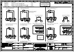
GNExCP7 CALL POINT
WIRING / CIRCUIT OPERATION DIAGRAM
D202-06-211
1
4
OF
5
GNExCP7
Addition of BG version ; options clarified
RNP 15-04-2022
R.N.POTTS
R.S.RAIT
05-03-2020
B.ISARD
1
2
3
4
5
6
M/S 1
7
8
KEY:
COM - Common
N/C - Normally Closed
(Contacts closed in unoperated state)
N/O - Normally Open
(Contacts open in unoperated state)
1
2
3
4
5
6
M/S 1
7
8
COM
N/O
WIRE LINK
1A - Circuit as shown in Unoperated condition
Terminals (4/5) & (7/8) open
Terminals (4/5) & (6) closed
DIODE
ZENER DIODE
POSITIVE (+) COMMON
(IF DIODES SUPPLIED & CONFIGURED BY E2S)
1
2
3
4
5
6
7
8
EOL
SER
M/S 1
Standard Unit withsuggested Series / EOL
Devices - Alternative Configuration
2A - Circuit as shown in Unoperated condition
Terminals (4/5) & (7/8) open
Terminals (4/5) & (6) closed
Standard Unit as supplied by E2S
Without Series / EOL Devices
N/C
COM
N/O
N/C
EOL
SER
1
2
3
4
5
6
M/S 1
7
8
COM
N/O
WIRE LINK
1B - Circuit as shown in Operated condition
Terminals (4/5) & (7/8) closed
Terminals (4/5) & (6) open
N/C
1
2
3
4
5
6
7
8
1
2
3
4
5
6
7
8
COM
N/O
N/C
COM
+
N/O
-
N/C
-
COM
+
N/O
-
N/C
-
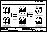
Standard Unit showing possitions
of optional Series / EOL Devices
1
2
3
4
5
6
M/S 1
7
8
2B - Circuit as shown in Operated condition
Terminals (4/5) & (7/8) closed
Terminals (4/5) & (6) open
COM
N/O
N/C
EOL
SER
NOTE: These can be fitted either
by customer or pre-installed by
E2S at point of order.
When fitting diodes or zener diodes, polarity
across devices must be observed
(Resistor polarity is unimportant)
SE
R
IE
S
EOL
Wiring option shown with EOL &
series devices acting in parallel
3A - Circuit as shown in Unoperated condition
Terminals (4/5) & (7/8) open
Terminals (4/5) & (6) closed
DIODE
ZENER DIODE
POSITIVE (+) COMMON
(IF DIODES SUPPLIED & CONFIGURED BY E2S)
1
2
3
4
5
6
7
8
1
2
3
4
5
6
7
8
COM
+
N/O
-
N/C
-
COM
+
N/O
-
N/C
-
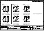
When fitting diodes or zener diodes, polarity
across devices must be observed
(Resistor polarity is unimportant)
SE
R
IES
EOL
Wiring option shown with EOL &
series devices acting in series
4
5
7
8
4
5
7
8
1
2
3
4
5
6
7
8
EOL
SER
M/S 1
COM
N/O
N/C
3B - Circuit as shown in Operated condition
Terminals (4/5) & (7/8) closed
Terminals (4/5) & (6) open
E2S PART NO.
GNExCP7-BG
GNExCP7-PB
GNExCP7-PM
GNExCP7-PT
DESCRIPTION
GNExCP7 Ex d GRP CALL POINT BREAK GLASS
GNExCP7 Ex d GRP CALL POINT PUSH BUTTON
GNExCP7 Ex d GRP CALL POINT MOMENTARY PUSH BUTTON
GNExCP7 Ex d GRP CALL POINT PUSH BUTTON TOOL RESET
DATA REFERENCE
1.24.150
1.24.180
1.24.170
1.24.160
GNExCP7 [ ] [S] [D]
SWITCH TYPE: [S] - Single Microswitch
TERMINAL TYPE [D] - DIN RAIL
FOR PERMITTED MIN/MAX
VALUES OF EOL & SERIES
DEVICES, PLEASE REFER TO
INSTRUCTIONS
05-03-2020
05-03-2020
ACN0102


