_______________________________________________________________________________________________________________________________
European Safety Systems Ltd.
Impress House, Mansell Road, Acton, London W3 7QH [email protected] Tel: +44 (0)208 743 8880
www.e-2-s.com Fax: +44 (0)208 740 4200
Document No. D202-00-001-IS Issue 1 25-04-2022 Sheet 3 of 7
T3 200
o
C
T4 135
o
C
T5 100ºC
T6
85ºC (GNExCP7-BG-D up to 65°C ambient)
Area Classification Dust
Zone 21
Explosive dust air mixture likely to occur in normal
operation.
Zone 22
Explosive dust air mixture not likely to occur in normal
operation, and if it does, it will only exist for a short time.
Dust Groupings
Group IIIA
Combustible Dusts
Group IIIB
Non-Conductive Dusts
Group IIIC
Conductive Dusts
Equipment Category
2G, 2D
Equipment Protection Level
Gb, Gc, Db, Dc
Maximum Surface Temperature for Dust Applications
80°C (GNExCP7-BG-S) ATEX/IECEx/UKEx
85°C (GNExCP7-BG-D) ATEX/IECEx/UKEx
110°C (GNExCP7-BG-S) Class Zone
135°C (GNExCP7-BG-D) Class Zone
Ambient Temperature Range
-55°C to +70°C (-67°F to +158°F)
IP Rating
IP66 to EN60529
4 / 4X / 3R / 13 to UL50E / NEMA250
Installation must be carried out in compliance with the latest
issue of the following standards:
EN60079-14 / IEC60079-14: Explosive atmospheres - Electrical
installations design, selection and erection
EN60079-10-1 / IEC60079-10-1: Explosive atmospheres -
Classification of areas. Explosive gas atmospheres
EN60079-10-2 / IEC60079-10-2: Explosive atmospheres -
Classification of areas. Explosive dust atmospheres
5) Specific Conditions for Safe Use
The stainless steel lift flap is not earthed and may generate
an ignition-capable level of electrostatic charges. It has a max
capacitance of 6.33pF according to CSA C22.2 NO. 60079-0
/ UL 60079-0:2017, clause 7.5 or EN/IEC60079-0, clause 7.5.
Equipment is permitted to be wall mounted only in vertical
position. The enclosure base is permitted in two mounting
positions, with the double entry lowermost or uppermost.
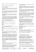
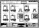
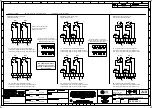
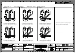
Fig 1 Wall mounting
Flame Path Positions
Flame Path on Base shown
hatched
Flame path through shaft bore
Flame Path on Cover Shown
Hatched
No repair to the Flamepaths is permitted
7) Location and Mounting
The location of the call point should enable ease of access
for operation and testing. The unit should be mounted using
the 4 off fixing holes which will accept up to M5 sized fixings.
They should only be fixed to services that can carry the
weight of the unit.
To gain access to the mounting holes in the base the front
cover must be removed. See Section 8.
Fig. 1 View of base unit showing fixing centres (in mm).
8) Access to the Flameproof Enclosure
To access the Ex d chamber, remove the four off M6 x 60
hexagon socket head screws and withdraw the flameproof
cover taking extreme care not to damage the flameproof
faces in the process. M6 cover screws are Class A4-70
stainless steel and only screws of this category can be used
for the enclosure.
Warning –
Hot surfaces. External surfaces
and internal components may be hot after
operation, take care when handling the
equipment.
Warning – High voltage may be present,
risk of electric shock. DO NOT open
when energised, disconnect power
before opening.


