European Safety Systems Ltd.
Impress House, Mansell Road, Acton, London W3 7QH
www.e2s.com
Tel: +44 (0)208 743 8880
Document No. D190-00-651-IS
Issue 2
06-03-2023
Sheet 13 of 15
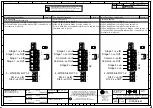
16-3 Header Pins Settings
J1 Header Pin - Position A
Factory default position (pins 1 & 2 not linked)
Places TB1 Current Sense Resistor (CSR) in circuit.
As used in 4 - Wire Configuration
J1 Header Pin - Position B
(pins 1 & 2 linked)
Removes TB1 Current Sense Resistor (CSR) out of circuit.
Figure 13: J1 Header pin positions
–
Current Sense Resistor (CSR)
J2 Header Pin - Position A
Factory default position (pins 1 & 2 linked)
Removes power supply terminal Fault Resistor (FR) & RLY 1-2 out
of circuit.
As used in 4 -Wire Configuration
J2 Header Pin - Position B
(pins 2 & 3 linked)
Places power supply terminal Fault resistor & RLY 1-2 in circuit.
As used in 2
–
Wire Configuration
Figure 14: J2 Header pin positions
–
Fault Resistor (FR)
16-4 SIL 2 Hard Reset Function
Power down the unit completely for a minimum of 30 seconds. Move the hard reset header pin (Jumper J3) to reset position B shown. Then power the
unit for a minimum of 5 seconds. Power down the unit for 30 seconds and then move the header pin back to Position A.
The unit has now been reset.
If the hard reset process does not correct the latched fault the alarm horn sounder may require further investigation, please contact your local E2S
representative.
J3 Header Pin - Position A
Factory default position (pins 2 & 3 linked)
Hard Reset Function disabled
–
Normal Operation
J3 Header Pin - Position B
(pins 1 & 2 linked)
Hard Reset Enabled - Active reset mode
Figure 15: J3 Header pin positions
–
Hard Reset Function


