background image

2

3

4

5

10

12

13

11

1

6

7

8

9

14

16

17

18

15

12

E-Tech W 

: 664Y6500 • B

en

4

EN

FR

NL

ES

IT

DE

PL

RU

INTRODUCTION

DESCRIPTION OF THE SPECIFICATIONS

This wall hung electric boiler is available in 7 models:

•  The models Single phase 09 and 15 are supplied with 230 V.

•  The models Tri phase 09, 15, 22, 28 and 36 are supplied with 400 V. 

The maximum power can be adjusted for all models by acting on 

the switches on the control panel.

The maximum power can be adjusted for this models by acting on 

the terminals bridges.

Adjustable power

MODELS

MIN

MAX

E-Tech W 09 - Single phase

5.6 kW

8.4 kW

E-Tech W 15 - Single phase

9.6 kW

14.4 kW

E-Tech W 22 - Tri phase

14.4 kW

21.6 kW

E-Tech W 22 - Tri phase

14.4 kW

28.8 kW

E-Tech W 36 - Tri phase

18 kW

36 kW

LINING

The boiler is protected by a steel lining that first of all undergoes a 

degreasing and phosphation process before being lacquered and 

burnt at 220°C.

HEATING BODY

The boiler heat exchanger is constructed from mild steel with welded 

joints. It is hydraulic tested under a pressure of 4.5 bar (maximum 

working pressure = 3 bar).

HEATING ELEMENTS

Immersion heaters, constructed from stainless steel Incoloy 800 and 

mounted in the top of the boiler, provide the power source for the 

Boiler.

EQUIPMENT

The boiler is equipped with all the necessary components to allow 

direct connection to a heating system without the need for a feed 

and expansion cistern. These components include; primary 10 litre 

expansion vessel (suitable for a system water content of up to 160 

litres), pressure and temperature gauge, safety valve, circulating 

pump, low water pressure switch, control and high limit thermostats, 

on/off and power level switches.

CONNECTION

The boiler is suitable for connection to most heating and hot water 

systems, with a maximum working pressure of 3 bar and a maximum 

temperature of 87°C. It can also be used in multiple boiler installations 

allowing greater outputs to be achieved.

The boiler, and connection glands for both the main power supply 

and optional external controls are provided, suitable for single or 

three phase electrical supply depending upon boiler output required.

An internal 3 amp MCB is provided to protect the internal control 

circuit, from which optional controls can be connected e.G. Internal 

or external timeclock.

CERTIFICATION

The boilers have been manufactured to comply with the following 

standards BS EN60335-2-35: 1998, BS EN55014-2:1997 and BS 

EN50081-1-1: 1992.

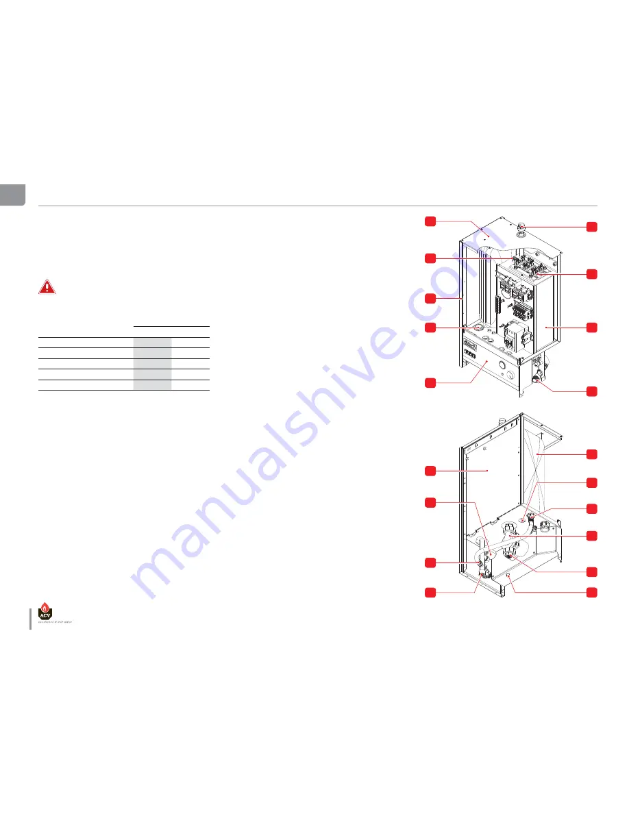
LEGEND

1.  Top cover
2.  Brass pocket
3.  Hand side panel
4.  Cable gland
5.  Control panel
6.  Automatic air vent
7.  Heating element
8.  Heating body
9.  Pressure safety valve
10.  Rear panel
11.  Water pressure switch
12.  Expansion vessel connection
13.  Heating return
14.  Expansion vessel
15.  Valve of expansion vessel
16.  Circulating pump
17.  Heating flow
18.  Manual reset hight limit thermostat

Summary of Contents for E-Tech W 09

Page 1: ...664Y6500 B EN FR NL ES IT DE PL RU INSTALLATION OPERATION AND MAINTENANCE INSTRUCTIONS 09 15 22 28 36 Single Tri Phase...

Page 2: ...mensions 10 Installation room 10 Disassembling 11 Heating connection 12 Heating connection dHW Y PLAN 12 Heating connection dHW S PLAN 12 Connecting the power supply 13 Connecting the electrical Acces...

Page 3: ...ommend that the boiler be handled by two people until it is securely fixed to a wall The safest route from the vehicle to the point of installation should be carefully assessed before unloading the bo...

Page 4: ...low direct connection to a heating system without the need for a feed and expansion cistern These components include primary 10 litre expansion vessel suitable for a system water content of up to 160...

Page 5: ...FR NL ES IT DE PL RU INTRODUCTION LEGEND 1 Relay 2 Timer 3 Control terminals 4 Circuit breaker 5 Safety switch 6 Power terminals with fuse 25A or 32A 7 Power terminals E Tech W 09 15 Single Phase E T...

Page 6: ...ng normal boiler operation depending on boiler temperature If the boiler is not in regular daily use during cold periods it is recommended that it be fitted with a frost sensing thermostat to override...

Page 7: ...working pressure bar 3 Min working pressure bar 0 8 Max working temperature C 87 Hydraulic pressure drop E Tech W 09 Single Tri mbar 10 E Tech W 15 Single Tri mbar 20 E Tech W 22 Tri mbar 45 E Tech W...

Page 8: ...14 4 Single Phase 9 6 kW 12 12 13 13 14 14 15 15 Terminal L1 A 20 8 20 8 41 6 Terminal N A 20 8 20 8 41 6 Power kW 4 8 4 8 9 6 ELECTRIC DATA OF MODEL 09 TRI PHASE STAGE 1 2 TOTAL Tri Phase 8 4 kW Term...

Page 9: ...al L3 A 20 8 20 8 41 6 Power kW 14 4 14 4 28 8 Tri phase 21 6 kW 12 12 13 13 14 14 15 15 Terminal L1 A 20 8 10 4 31 2 Terminal L2 A 20 8 10 4 31 2 Terminal L3 A 20 8 10 4 31 2 Power kW 14 4 7 2 21 6 E...

Page 10: ...suitable external frost thermostat should be fitted CONNECTING TO THE SYSTEM the boiler is designed to operate on a sealed system ie no open vent or feed and expansion cistern Hot water expansion with...

Page 11: ...DISASSEMBLING Panel removal and access to hydraulic connections 1 Undo screws 2 Tilt panel towards you and lift clear remove the top cover 3 Loosen screws of the control panel 4 Turn up the control pa...

Page 12: ...9 2 8 27 26 25 24 23 2 2 2 1 1 9 40 2 0 1 8 17 16 15 14 13 1 2 1 1 9 3 0 1 0 8 7 6 5 4 3 2 1 3 9 3 8 37 36 35 34 33 3 2 3 1 2 9 2 8 27 26 25 24 23 2 2 2 1 1 9 40 2 0 1 8 17 16 15 14 13 1 2 1 1 9 3 0 1...

Page 13: ...0 Hz en 13 E Tech W 664Y6500 B EN FR NL ES IT DE PL RU INSTALLATION CONNECTING THE POWER SUPPLY This appliance must be permanently connected to fixed wiring and must be earthed The wiring must be carr...

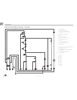
Page 14: ...or controller supply optional 3 4 DHW kit optional 5 6 Stop Bridge or time clock switch control optional 7 8 Room thermostat optional 9 10 11 Heating pump 12 13 Relay K3 deactivated 1 2 Time clock or...

Page 15: ...insulation the wires canalisation the mounting and the environment The following values are given for information for an ambient temperature of 30 C and a maximal length of 5 meters In all the cases t...

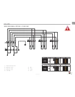
Page 16: ...H W 09 15 SINGLE PHASE CB Circuit breaker S1 ON OFF switch lamp S2 Manual reset safety thermostat 103 C PS Low water pressure switch DS1 Alarm S3 Control thermostat S4 Power switch level 1 lamp K1 Pow...

Page 17: ...DE PL RU INSTALLATION POWER WIRING DIAGRAM E TECH W 09 15 SINGLE PHASE E Tech W 09 8 4 kW 5 6 kW Single Phase TB1 12 12 13 13 14 14 15 15 12 12 13 13 14 14 15 15 E Tech W 15 14 4 kW 9 6 kW Single Phas...

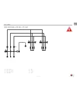
Page 18: ...IRING DIAGRAM E TECH W 09 15 TRI PHASE CB Circuit breaker S1 ON OFF switch lamp S2 Manual reset safety thermostat 103 C PS Low water pressure switch DS1 Alarm S3 Control thermostat S4 Power switch lev...

Page 19: ...k R Or Bk R Or B B B B B B Bk R Or Bk R en 19 E Tech W 664Y6500 B EN FR NL ES IT DE PL RU INSTALLATION POWER WIRING DIAGRAM E TECH W 09 15 TRI PHASE S6 Power terminals K1 Power relay 1 level 1 K2 Powe...

Page 20: ...TECH W 22 TRI PHASE CB Circuit breaker S1 ON OFF switch lamp S2 Manual reset safety thermostat 103 C PS Low water pressure switch DS1 Alarm S3 Control thermostat S4 Power switch level 1 lamp K1 Power...

Page 21: ...Bk R R en 21 E Tech W 664Y6500 B EN FR NL ES IT DE PL RU INSTALLATION POWER WIRING DIAGRAM E TECH W 22 TRI PHASE E Tech W 22 21 6 kW 14 4 kW Tri Phase TB1 12 12 13 13 14 14 15 15 12 12 13 13 14 14 15...

Page 22: ...SE CB Circuit breaker S1 ON OFF switch lamp S2 Manual reset safety thermostat 103 C PS Low water pressure switch DS1 Alarm S3 Control thermostat S4 Power switch level 1 lamp K1 Power relay 1 level 1 K...

Page 23: ...Tech W 664Y6500 B EN FR NL ES IT DE PL RU INSTALLATION POWER WIRING DIAGRAM E TECH W 28 TRI PHASE E Tech W 28 28 8 kW 21 6 kW 14 4 kW Tri Phase TB1 12 12 13 13 14 14 15 15 12 12 13 13 14 14 15 15 12 1...

Page 24: ...SE CB Circuit breaker S1 ON OFF switch lamp S2 Manual reset safety thermostat 103 C PS Low water pressure switch DS1 Alarm S3 Control thermostat S4 Power switch level 1 lamp K1 Power relay 1 level 1 K...

Page 25: ...R R en 25 E Tech W 664Y6500 B EN FR NL ES IT DE PL RU INSTALLATION POWER WIRING DIAGRAM E TECH W 36 TRI PHASE E Tech W 36 36 kW 27 kW 18 kW Tri Phase TB1 12 12 13 13 14 14 15 15 12 12 13 13 14 14 15 1...

Page 26: ...7 8 9 10 V4043H DHW ZONE VALVE MOTOR Honeywell Sundial Wiring Centre S Plan Note Earth wires not shown for clarity During installation the earth wires from each component connect to terminal 3 in the...

Page 27: ...wires from each component connect to terminal 3 in the wiring centre bk black br brown r red w white y yellow o orange b blue v violet p pink gr grey CABLE COLOUR CODES gr b b b o 1 2 C HW OFF V4073A...

Page 28: ...stage 1 the first stage contactors will energise 6 Switch on the power levels switch stage 2 after a short delay the second stage contactors will energise Note the power stage delay timer settings sh...

Page 29: ...en 29 E Tech W 664Y6500 B EN FR NL ES IT DE PL RU REMOVAL THE HEATING ELEMENTS 3 1 2...

Page 30: ...E Tech W 664Y6500 B en 30 EN FR NL ES IT DE PL RU...

Reviews: