background image

E-Tech W 

: 664Y6500 • B

en

28

EN

FR

NL

ES

IT

DE

PL

RU

COMMISSIONING AND MAINTENANCE

COMMISSIONING - WATER

1.  The system must be thoroughly cleansed prior to connection 

of the boiler. The system water should be treated to prevent 

general corrosion and deposition of scale or sludge in the boiler, 

please refer to BS7593. If installing the boiler into an existing 

system, ACV recommend that an approved system cleaner is 

used.

2.   Fill and pressurise the boiler and system to 1.5 bar, making sure 

to vent the boiler via the automatic air vent on top of the boiler. 

Note that the black dust cap on the air vent should be left loose 

to allow the auto vent to function.

3.  Check for leaks.

4.  For specialist advice on water treatment products, contact:


Fernox, Britannia Works


Clavering, Essex CB11 4QZ


Tel 01799 550811

COMMISSIONING - ELECTRICAL

The Electrical installation supplying this boiler must conform to the 

current IEE Regulations.

1.  Remove the front panel and check all electrical connections for 

tightness.

2.  Ensure all internal relays, contactors etc are secure on the DIN 

rails.

3.  Set all panel control switches to off.

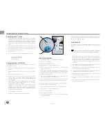
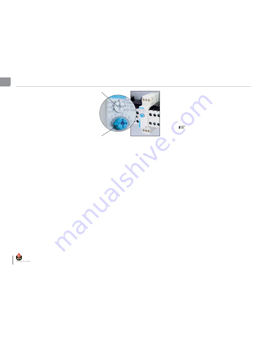
4.  Check the power stage delay timer settings - Adjuster (

A

is factory set to the 1 to 10 minute position which is the 

optimum setting for the boiler and should be verified during 

commissioning.


Adjuster (

B

) is used to set the DELAY ON time of the following 

stage contactors, the available settings are in 1 minute 

increments if A is set to 1 to 10 minutes.

  This function is particularly useful in areas where gradual 

switching of electrical load is required and the resulting 

maximum demand kept to a minimum. The timers add to the 

flexibility of the installation but must be optimised by a qualified 

engineer. The normal setting is 1.

5.  Set internal MCB to off position.

6.  Set the control thermostat to desired temperature.

STARTING THE BOILER

1.  Switch on the internal or external timeclock (if fitted).

2.  Switch on internal MCB.

3.  Switch on local isolator to boiler.

4.  Turn the boiler on using the ON/OFF switch.

5.  Switch on the power levels switch stage 1, the first stage 

contactors will energise.

6.  Switch on the power levels switch stage 2, after a short delay the 

second stage contactors will energise. Note: the power stage 

delay timer settings should be verified as shown in item 4 under 

“Commissioning - Electrical”.

7.  The boiler temperature will now rise as indicated by the 

combined temperature and pressure gauge.

8.  The temperature will continue to rise until the control thermostat 

temperature setting is reached then the boiler will switch off.

Once these procedures have been followed the system can be left to 

operate normally by the following method.

1.  Ensure that boiler thermostat is set to the desired temperature.

2.  Turn the boiler on using the ON/OFF switch.

3.  Turn on power level switch 1.

4.  Turn on power level switch 2.

5.  Set timeclock (if fitted) and/or external controls to desired boiler 

operating on/off times.

B

A

After one week of operation all electrical connections should be re-

checked for tightness and the boiler water system checked for leaks 

and air and rectified if necessary.

MAINTENANCE

For safety reasons it is recommended that the boiler is serviced 

annually and that servicing is carried out by a qualified service 

engineer.

  Before carrying out any work on the system ensure that 

the boiler is cool and all electrical supplies are isolated.

1.   After removing front cover undo the four screws retaining the 

front control panel and gently let the panel suspend on the 

wiring to the rear of the panel. Undertake a visual inspection 

of the boiler looking out for signs of water leakage from joints, 

expansion vessel, and the area around the elements on top of 

the boiler.

2.  Undertake a visual inspection of all cabling in the boiler casing 

checking for signs of overheating or burning.

3.  Check all push-on electrical connectors for tightness and good 

connection to the relative components.

4.  Using a correct fitting screwdriver check all electrical terminals 

on DIN rails and on all components for tightness.

5.  Check the settings on the internal timers in accordance with the 

“Commissioning - Electrical” section.

6.  Replace the control panel and the boiler front cover and refit 

screws.

7.  Reinstate the electrical supply and follow the procedures set out 

in the commissioning section.

Summary of Contents for E-Tech W 09

Page 1: ...664Y6500 B EN FR NL ES IT DE PL RU INSTALLATION OPERATION AND MAINTENANCE INSTRUCTIONS 09 15 22 28 36 Single Tri Phase...

Page 2: ...mensions 10 Installation room 10 Disassembling 11 Heating connection 12 Heating connection dHW Y PLAN 12 Heating connection dHW S PLAN 12 Connecting the power supply 13 Connecting the electrical Acces...

Page 3: ...ommend that the boiler be handled by two people until it is securely fixed to a wall The safest route from the vehicle to the point of installation should be carefully assessed before unloading the bo...

Page 4: ...low direct connection to a heating system without the need for a feed and expansion cistern These components include primary 10 litre expansion vessel suitable for a system water content of up to 160...

Page 5: ...FR NL ES IT DE PL RU INTRODUCTION LEGEND 1 Relay 2 Timer 3 Control terminals 4 Circuit breaker 5 Safety switch 6 Power terminals with fuse 25A or 32A 7 Power terminals E Tech W 09 15 Single Phase E T...

Page 6: ...ng normal boiler operation depending on boiler temperature If the boiler is not in regular daily use during cold periods it is recommended that it be fitted with a frost sensing thermostat to override...

Page 7: ...working pressure bar 3 Min working pressure bar 0 8 Max working temperature C 87 Hydraulic pressure drop E Tech W 09 Single Tri mbar 10 E Tech W 15 Single Tri mbar 20 E Tech W 22 Tri mbar 45 E Tech W...

Page 8: ...14 4 Single Phase 9 6 kW 12 12 13 13 14 14 15 15 Terminal L1 A 20 8 20 8 41 6 Terminal N A 20 8 20 8 41 6 Power kW 4 8 4 8 9 6 ELECTRIC DATA OF MODEL 09 TRI PHASE STAGE 1 2 TOTAL Tri Phase 8 4 kW Term...

Page 9: ...al L3 A 20 8 20 8 41 6 Power kW 14 4 14 4 28 8 Tri phase 21 6 kW 12 12 13 13 14 14 15 15 Terminal L1 A 20 8 10 4 31 2 Terminal L2 A 20 8 10 4 31 2 Terminal L3 A 20 8 10 4 31 2 Power kW 14 4 7 2 21 6 E...

Page 10: ...suitable external frost thermostat should be fitted CONNECTING TO THE SYSTEM the boiler is designed to operate on a sealed system ie no open vent or feed and expansion cistern Hot water expansion with...

Page 11: ...DISASSEMBLING Panel removal and access to hydraulic connections 1 Undo screws 2 Tilt panel towards you and lift clear remove the top cover 3 Loosen screws of the control panel 4 Turn up the control pa...

Page 12: ...9 2 8 27 26 25 24 23 2 2 2 1 1 9 40 2 0 1 8 17 16 15 14 13 1 2 1 1 9 3 0 1 0 8 7 6 5 4 3 2 1 3 9 3 8 37 36 35 34 33 3 2 3 1 2 9 2 8 27 26 25 24 23 2 2 2 1 1 9 40 2 0 1 8 17 16 15 14 13 1 2 1 1 9 3 0 1...

Page 13: ...0 Hz en 13 E Tech W 664Y6500 B EN FR NL ES IT DE PL RU INSTALLATION CONNECTING THE POWER SUPPLY This appliance must be permanently connected to fixed wiring and must be earthed The wiring must be carr...

Page 14: ...or controller supply optional 3 4 DHW kit optional 5 6 Stop Bridge or time clock switch control optional 7 8 Room thermostat optional 9 10 11 Heating pump 12 13 Relay K3 deactivated 1 2 Time clock or...

Page 15: ...insulation the wires canalisation the mounting and the environment The following values are given for information for an ambient temperature of 30 C and a maximal length of 5 meters In all the cases t...

Page 16: ...H W 09 15 SINGLE PHASE CB Circuit breaker S1 ON OFF switch lamp S2 Manual reset safety thermostat 103 C PS Low water pressure switch DS1 Alarm S3 Control thermostat S4 Power switch level 1 lamp K1 Pow...

Page 17: ...DE PL RU INSTALLATION POWER WIRING DIAGRAM E TECH W 09 15 SINGLE PHASE E Tech W 09 8 4 kW 5 6 kW Single Phase TB1 12 12 13 13 14 14 15 15 12 12 13 13 14 14 15 15 E Tech W 15 14 4 kW 9 6 kW Single Phas...

Page 18: ...IRING DIAGRAM E TECH W 09 15 TRI PHASE CB Circuit breaker S1 ON OFF switch lamp S2 Manual reset safety thermostat 103 C PS Low water pressure switch DS1 Alarm S3 Control thermostat S4 Power switch lev...

Page 19: ...k R Or Bk R Or B B B B B B Bk R Or Bk R en 19 E Tech W 664Y6500 B EN FR NL ES IT DE PL RU INSTALLATION POWER WIRING DIAGRAM E TECH W 09 15 TRI PHASE S6 Power terminals K1 Power relay 1 level 1 K2 Powe...

Page 20: ...TECH W 22 TRI PHASE CB Circuit breaker S1 ON OFF switch lamp S2 Manual reset safety thermostat 103 C PS Low water pressure switch DS1 Alarm S3 Control thermostat S4 Power switch level 1 lamp K1 Power...

Page 21: ...Bk R R en 21 E Tech W 664Y6500 B EN FR NL ES IT DE PL RU INSTALLATION POWER WIRING DIAGRAM E TECH W 22 TRI PHASE E Tech W 22 21 6 kW 14 4 kW Tri Phase TB1 12 12 13 13 14 14 15 15 12 12 13 13 14 14 15...

Page 22: ...SE CB Circuit breaker S1 ON OFF switch lamp S2 Manual reset safety thermostat 103 C PS Low water pressure switch DS1 Alarm S3 Control thermostat S4 Power switch level 1 lamp K1 Power relay 1 level 1 K...

Page 23: ...Tech W 664Y6500 B EN FR NL ES IT DE PL RU INSTALLATION POWER WIRING DIAGRAM E TECH W 28 TRI PHASE E Tech W 28 28 8 kW 21 6 kW 14 4 kW Tri Phase TB1 12 12 13 13 14 14 15 15 12 12 13 13 14 14 15 15 12 1...

Page 24: ...SE CB Circuit breaker S1 ON OFF switch lamp S2 Manual reset safety thermostat 103 C PS Low water pressure switch DS1 Alarm S3 Control thermostat S4 Power switch level 1 lamp K1 Power relay 1 level 1 K...

Page 25: ...R R en 25 E Tech W 664Y6500 B EN FR NL ES IT DE PL RU INSTALLATION POWER WIRING DIAGRAM E TECH W 36 TRI PHASE E Tech W 36 36 kW 27 kW 18 kW Tri Phase TB1 12 12 13 13 14 14 15 15 12 12 13 13 14 14 15 1...

Page 26: ...7 8 9 10 V4043H DHW ZONE VALVE MOTOR Honeywell Sundial Wiring Centre S Plan Note Earth wires not shown for clarity During installation the earth wires from each component connect to terminal 3 in the...

Page 27: ...wires from each component connect to terminal 3 in the wiring centre bk black br brown r red w white y yellow o orange b blue v violet p pink gr grey CABLE COLOUR CODES gr b b b o 1 2 C HW OFF V4073A...

Page 28: ...stage 1 the first stage contactors will energise 6 Switch on the power levels switch stage 2 after a short delay the second stage contactors will energise Note the power stage delay timer settings sh...

Page 29: ...en 29 E Tech W 664Y6500 B EN FR NL ES IT DE PL RU REMOVAL THE HEATING ELEMENTS 3 1 2...

Page 30: ...E Tech W 664Y6500 B en 30 EN FR NL ES IT DE PL RU...

Reviews: