


- 5 -
USER DATA
All user controls are situated on the front panel of the boiler, there
are no user controls inside the boiler casing.
The following instructions assume that the boiler has been
commissioned, and that the system is filled with water and has
been fully vented.
SETTING UP
• Before switching on any electrical supplies to the boiler ensure
that the combined temperature and pressure gauge reads at
least 1 bar and the control thermostat is set to the desired
temperature.
• If an internal time clock is fitted ensure that this is switched on
(see “Optional Internal Time Clock”) and if any other auxiliary
controls are fitted e.g. programmer, room thermostats, cylinder
thermostats etc, consult appropriate manufacturers' instructions
to switch these on.
• Switch on any local means of isolation to boiler.
• Switch the boiler on using the
ON/OFF
switch (the neon light on
the switch should now glow).
• Turn on both power level switches - after a short period of time
the boiler temperature should start to rise, indicated by the
combined temperature and pressure gauge. If the boiler fails to
operate, the overheat safety thermostat should be checked.
Access to the thermostat reset button is obtained by unscrewing
(anti-clockwise) the domed button cover on the front panel
(a screwdriver is not required).The reset button can then be
seen - press the button, a click should be heard and the button
is reset. If no click was heard the device is not at fault and
further investigation is required by a suitably qualified engineer.
• The internal clock or external programmer can now be set to
allow on/off periods as desired. The ON/OFF switch and 2 power
level switches should be left in the ON position during normal use.
the power level switches will automatically switch on and
off during normal boiler operation, depending on boiler
temperature.
• If the boiler is not in regular daily use during cold periods, it is
recommended that it be fitted with a frost sensing thermostat to
override the timeclock and prevent the system from freezing.
• As with most boilers and heating appliances the casing and
pipework can get hot during normal running so the boiler must
not be covered and the surrounding area must be kept clear.
OPTIONAL INTERNAL TIMECLOCK
• This operates on a 24-hour sequence. Around- the outside of the
clock there are a number of white tabs - these allow 15 minute
switching times.To set a boiler cycle simply push outwards the
number of tabs required for your heating period.
Remember : tab OUT = BOILER ON
tab IN
= BOILER OFF
The time of day is marked by an arrow on the inner part of the clock
- set the outer time to coincide with this arrow.
On the centre part of the clock there is a switch.
This has three positions :
• Switch down - timeclock off
• Switch middle - timeclock timed (normal position)
• Switch up - timeclock on constant.
PRESSURE IN THE HEATING SYSTEM
The CH pressure must be a minimum of 1 bar and must be checked
by the end user on a regular basis. If the pressure drops under 0.5
bar, the integrated water pressure switch blocks the appliance until
the pressure in the system returns to a level above 0.8 bar.
The installer fits the system with a separate fill valve underneath the
appliance. Make sure that the appliance is powered off when filling
the system. To do this, turn the on/off switch.
For more information, please ask your installer when the system is
delivered.
A safety valve is provided underneath the appliance. If the system
pressure exceeds 3 bars, this valve opens and drains the water
from the system. In this case, please contact your installer.
INSTRUCTIONS
1
2
3
5
4
6
7
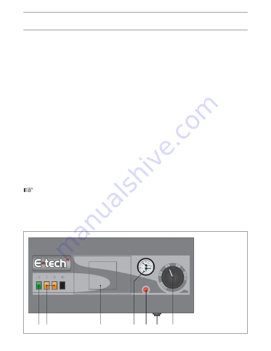
LEGEND
1. ON/OFF switch
2. Power levels switch
3. Optional internal
clock or controler
4. Combined temperature
and pressure gauge
5. Boiler shutdown
indicator light
6. Manual reset high
limit thermostat
7. Control thermostat :
1 = 40°C
2 = 50°C
3 = 60°C
4 = 70°C
5 = 80°C


