Flight Preparation
Control Directions
1. Connect the throttle lead from the ESC to the receiver.
2. Connect the wing servos to the receiver with two 3” extension leads
(JSP98100) if using the dual aileron function in your transmitter, otherwise use
a Y-harness (JSP98020). Attach the wing to the model.
3. Connect battery power to the ESC and using your radio verify the correct
rotation of the motor. Viewed in the direction of flight, the propeller should
rotate clockwise. We have printed an E-tip regarding the switching direction of
your motor on page 15 for reference.
4. Center the trims on your transmitter and check that the control surfaces are
neutral. Large adjustments should be made at the control surface by adjusting
the clevis, fine-tuning can be done using the transmitter subtrim function.
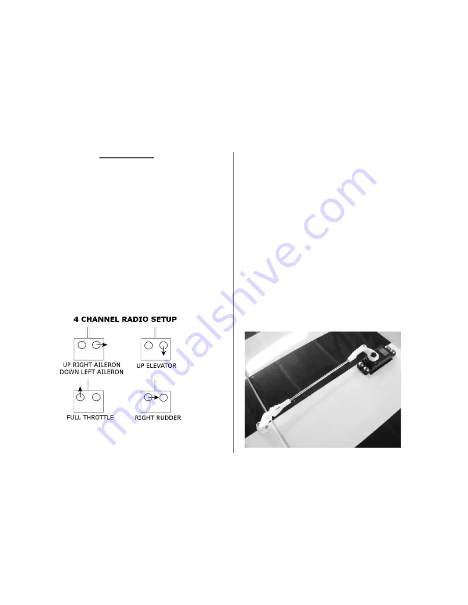
5. Verify that the control surfaces operate in the correct direction using the
following diagram. Use the servo reversing function in your transmitter as
necessary to correct the direction of motion.
Control Throws
Use a ruler to set the control throws for the ailerons, rudder and elevator. The
position of the pushrod can be altered at either the servo or control surface to
adjust the amount of control throw. Moving the pushrod closer to the center of
the servo, or further from the control surface, will have the effect of reducing
surface travel, and vice versa.
These measurements are taken at the widest part of the control surface. They
are a general guide from our own flight testing and you can experiment with
more or less throw to suit your preferred flying style.
Low Rate
Aileron
3/8” (10mm) up and down
Elevator
7/8” (22mm) up and down
Rudder
2”
(50mm) left and right
High Rate
Aileron
5/8” (16mm) up and down
Elevator
1-1/8” (29mm) up and down
Rudder
2-1/2” (64mm) left and right
Once you have set the control throws, install the silicone keepers on all the
clevises. This will prevent any possible failure in flight of a clevis popping
loose.
27


