background image

26

Ο

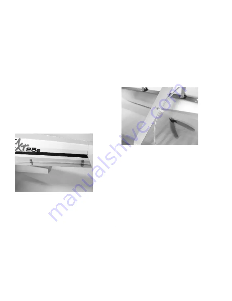
11. Use the two remaining full brass straps to attach the pushrod tube to the

left side of the Pulse fuselage. Locate the straps as shown in the picture below

using the following dimensions as a guide. There are fuselage frames at these

locations; ensure that the screws are located in the center of the frame and will

not interfere with any internal items such as pushrods.

Aft strap: approximately 3/8” forward of stabilizer leading edge, and

centered 9/16” up from bottom of fuselage.

Forward strap: approximately 6-1/2” forward of stabilizer leading edge, and

5/8” up from bottom of fuselage.

Use a 1/16” drill bit and pin drill to make the holes for the 2mm x 10mm

screws. Strengthen each hole with a small drop of thin CA and allow to cure.

Using a #0 Philips screwdriver, attach the straps over the pushrod tube with

both the air and water rudders centered.

13. Refer to page 16 in the Float Set assembly manual to finalize the

installation of the floats. This will involve final adjustment of linkages to ensure

that the rudder is aligned and operates correctly.

It is extremely important that you verify the center of gravity is still correct with

the floats installed. It will be more accurate to check the CG of your float

equipped Pulse with the model

right side up

, as opposed to inverted when the

wheels are installed.

Pages 26 and 27 of your Float Set assembly manual include some tips for

flying from floats. If you are a first-time water flier, please take the time to read

these pages before heading out to the lake.

Ο

12. Attach the water rudder cable housing to the left float mount strut using

the cable tie provided in the Float Set hardware bag. Trim the excess tie

material using cutters or a blade.

Summary of Contents for Pulse XT 25e ARF

Page 1: ...Pulse XT 25e ARF Assembly Manual...

Page 2: ...classic Hangar 9 Pulse 40 XT This is a great flying sport ARF that s perfect for intermediate pilots and sport fliers who want to fly an airplane that s more aerobatic than high wing airplanes Based...

Page 3: ...our model This is also a good time to check through the list of required parts and tools and obtain any items not on hand that you may need to complete the model Inspection Before beginning assembly o...

Page 4: ...ner motor EFLM4025A E flite 40 Amp Pro Brushless ESC EFLA1040 E flite 3200mAh 3S LiPo battery pack EFLB32003S APC 12 x 8E propeller APC12080E High Power Motor Setup E flite Power 32 brushless outrunne...

Page 5: ...g approximately 1 4 protruding from the wheel collar Approximately 1 total axle length is the longest that will fit within the wheel pant A cutoff wheel in a rotary tool works well for this Do this fo...

Page 6: ...metal screws An accurate method of aligning the wheel pants to the fuselage is to level the fuselage with a block under the rear end then support the wheel pant with another block while marking the l...

Page 7: ...d the fin post will slide between the aft fuselage sides 3 Install the two washers and retaining nuts with a 1 4 nut driver or wrench Tighten them enough that the tail assembly is seated fully and is...

Page 8: ...ip pen Sidecutters 1 Prepare the fuselage servos by installing the rubber grommets and brass bushings in the mounting lugs Place the servos in the fuselage and mark the screw hole locations using a fe...

Page 9: ...a 1 Philips screwdriver 5 Install the clevises and silicone keepers on the pushrods as shown then install the pushrods in the fuselage from their openings in the rear fuselage sides JR s MatchMaker is...

Page 10: ...t tip pen Place a 90 degree bend towards the bottom of the fuselage in each of the pushrods in this location Install the nylon keepers on the pushrods at the servo arms Trim the remaining wire using s...

Page 11: ...4 4 40 x 1 2 socket head bolts Adhesive backed hook and loop tape 2 Hook and loop straps Required Tools 3 32 balldriver 1 Philips screwdriver Threadlock N No ot te e Your E flite Pulse XT 25e has bee...

Page 12: ...It can then be pulled rearwards and off the model 4 Install the battery with two hook and loop straps Slots are provided on the floor of the battery compartment for the straps to pass through The natu...

Page 13: ...he rear of the motor using the countersunk Philips head screws included with the motor You may use threadlock to prevent these screws vibrating loose during flight 2 Using a 3 32 balldriver install th...

Page 14: ...through The natural curl of the straps will allow them to be fed down one slot under the battery compartment floor then up through the opposite slot Should you find that the rotation direction of you...

Page 15: ...river install the cowling with four 4 40 x 1 4 socket head bolts and four 4 steel washers 2 The spinner backplate requires the hole to be enlarged to suit the propeller adapter For a snug fit on the p...

Page 16: ...method to drilling completely through the spinner backplate is to grind only the relief necessary to clear the propeller adapter hub This can be done by hand using a straight cutter in a Dremel rotary...

Page 17: ...s Rubbing alcohol Paper towels 1 Install the leading edge dowels in the wing panels with 12 minute epoxy Use paper towels and rubbing alcohol to clean any epoxy that squeezes out onto the wing 2 Upon...

Page 18: ...piece of clear tape to the front and rear wing saddle area where the wing leading and trailing edges will come in contact with the fuselage 6 12 minute epoxy is used to install the dihedral joiners a...

Page 19: ...th a paper towel 9 Allow the glue to dry then remove the wing from the fuselage Remove the tape from the wing and fuselage Aileron Servo Installation Required Parts 2 servos and hardware 2 6 servo ext...

Page 20: ...to prevent them falling back into the wing 3 Place the servos in the wing openings and mark the screw hole locations with a felt tip pen 4 Using a 1 16 in 1 5mm drill bit in a pin drill drill the four...

Page 21: ...end the pushrod up away from the wing surface at this location and install it on the servo arm with a pushrod keeper 6 Using a 1 Philips screwdriver remove the servo horn Using sidecutters remove thre...

Page 22: ...nd install on the fuselage Tape can be used to hold it in place while the glue dries Allow the glue to dry completely before removing the tape 2 Follow the same procedure to attach the cooling exit sc...

Page 23: ...Pulse are the wire float mount the sub fin and the water rudder pushrod Refer to the Float Set assembly manual in addition to these instructions for reference when assembling the floats 2 Using a 1 Ph...

Page 24: ...m Allen wrench provided in the float kit Make sure to use threadlock when installing the setscrews in the flats made previously Note One of the floats has holes drilled in the aft end for the water ru...

Page 25: ...and tube need to be cut to length prior to installation The cable length will be approximately 31 5 in and the tube length approximately 26 5 in With the pushrod cable inside the pushrod tube attach t...

Page 26: ...ips screwdriver attach the straps over the pushrod tube with both the air and water rudders centered 13 Refer to page 16 in the Float Set assembly manual to finalize the installation of the floats Thi...

Page 27: ...ng the following diagram Use the servo reversing function in your transmitter as necessary to correct the direction of motion Control Throws Use a ruler to set the control throws for the ailerons rudd...

Page 28: ...forward will have the opposite effect Preflight Battery Charging Use the recommended charger for the batteries being used in your radio and model and follow the charging instructions If using Lithium...

Page 29: ...0 E flite 1 5 Cell LiPo Charger with Balancer An Intelligent Balance Charger for 1 5 cell LiPo or Li Ion batteries Features a large 2 line backlit LCD display polarity protection and a safety timer Ch...

Page 30: ...6 Channel Radio by Spektrum The 6 channel DX6i uses the same DSM2 technology found in the Spektrum DX7 and includes an impressive list of programming features for both airplanes and helicopters that...

Page 31: ...thium Polymer charger only Do not use a NiCd or NiMH charger failure to do so may cause a fire which may result in personal injury and or property damage Never charge around or in the area of any flam...

Page 32: ...comes in contact with the battery If the battery is undamaged but no longer useful 1 Discharge the battery to a maximum of 2 5V using a slow safe discharge method 2 Leave battery discharged and retes...

Page 33: ...lmets must be properly worn and fastened They must be OSHA DOT ANSI SNELL or NOCSAE approved or comply with comparable standards RADIO CONTROL 1 All model flying shall be conducted in a manner to avoi...

Page 34: ...nt Damage Limits HORIZON SHALL NOT BE LIABLE FOR SPECIAL INDIRECT OR CONSEQUENTIAL DAMAGES LOSS OF PROFITS OR PRODUCTION OR COMMERCIAL LOSS IN ANY WAY CONNECTED WITH THE PRODUCT WHETHER SUCH CLAIM IS...

Page 35: ...e agreeing to payment of the repair without notification Repair estimates are available upon request You must include this request with your repair Non warranty repair estimates will be billed a minim...

Page 36: ...2008 Horizon Hobby Inc 4105 Fieldstone Road Champaign Illinois 61822 877 504 0233 horizonhobby com E fliteRC com...

Reviews: