background image

Available from:

www.modelflight.com.au

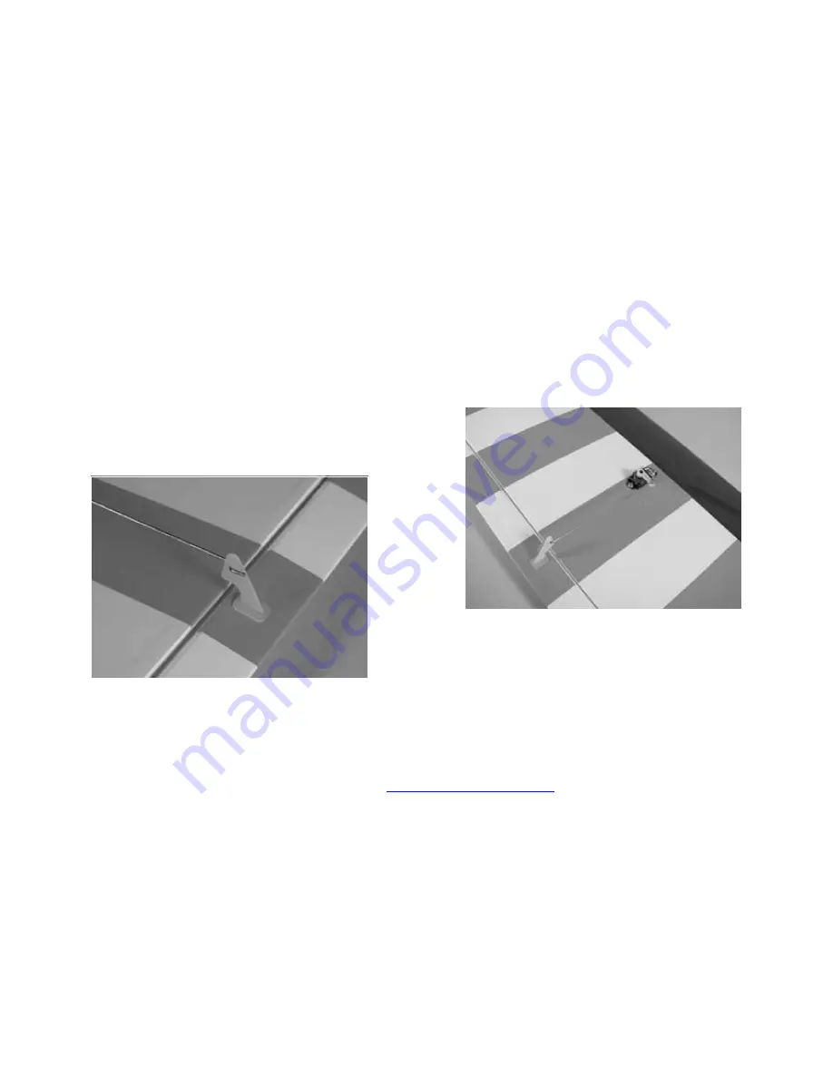
2. Drill a 1/16" (1.5mm) hole in the servo arm

for the pushrod connector. Secure the control
connector in the servo arm using the connector
backplate.

3. Locate the 4

1

/

4

" (118mm) linkage. Place the

“Z” bend into the center hole of the aileron
control horn. Pass the linkage through the
control connector.

4. Plug the aileron servo into the receiver. Power

up the transmitter and receiver. Center the aileron
stick, trim, and any programmed sub-trim values.
Install the arm on the servo so it is parallel to the
aileron hinge line. Use a 2mm x 4mm screw to
secure the linkage.

5. Repeat Steps 1 through 4 for the remaining

aileron servo. Then connect a 6" Y-harness to the
two 6" servo extensions on the servos.

25

Summary of Contents for Mini Pulse XT

Page 1: ...A v a i l a b l e f r o m w w w m o d e l f l i g h t c o m a u Mini Pulse XT Assembly Manual...

Page 2: ...7 Limited Warranty Period 8 Limited Warranty Limits of Liability 8 Safety Precautions 9 Questions Assistance and Repairs 9 Questions or Assistance 9 Inspection or Repairs 9 Warranty Inspection and Re...

Page 3: ...e factory to help speed up the building time Specifications Wingspan 42 5 in 1080mm Length 37 5 in 875mm Wing Area 330 sq in 21 5 sq dm Weight w o Battery 21 22 oz 710 820 g Weight w Battery 25 27 oz...

Page 4: ...L2377 Fuselage EFL2378 Tail Set EFL2380 Main Landing Gear EFL2381 Cowling EFL2382 Wheel Pants Small Replacement Parts EFL2379 Pushrod Set EFL2383 Motor X Mount EFLA200 Micro Control Horns FLA203 Micro...

Page 5: ...460 DX6 DSM 6CH Park Flyer w 4 S75 Servos Note We recommend the crystal free interference free Spektrum DX6 2 4GHz DSM 6 Channel System which includes a micro receiver and 4 sub micro servos Or JSP306...

Page 6: ...THP21003SPL 2100mAh 3 Cell 11 1V Li Po 16GA Or EFLB1035 11 1V 2100mAh 3 Cell Li Po 16GA EFLP1080E 10 x 8 Electric Prop EFLAEC302 EC3 Battery Connector Female 2 EFLC3005 Celectra 1 to 3 cell Li Po Cha...

Page 7: ...nd reinstall the hinges surfaces Note on Lithium Polymer Batteries Lithium Polymer batteries are significantly more volatile than alkaline or Ni Cd Ni MH batteries used in RC applications All manufact...

Page 8: ...case shall Horizon Hobby s liability exceed the original cost of the purchased product and will not cover consequential incidental or collateral damage Horizon Hobby Inc reserves the right to inspect...

Page 9: ...ontact Horizon Hobby Inc directly This will enable Horizon to better answer your questions and service you in the event that you may need any assistance Questions or Assistance For questions or assist...

Page 10: ...freight for non warranty repairs Please advise us of your preferred method of payment Horizon Hobby accepts money orders and cashiers checks as well as Visa MasterCard American Express and Discover c...

Page 11: ...necessary to always keep a safe distance in all directions around your model as this margin will help to avoid collisions or injury Always operate your model in an open area away from cars traffic or...

Page 12: ...quired Tools and Adhesives Hex wrench 3 32 Phillips screwdriver small Nut driver 1 4 Needle nose pliers Note You may consider using a larger diameter wheel such as 2 1 4 58mm if your flying site has r...

Page 13: ...This washer will fit inside the wheel pant 3 Fit the assembly in Step 2 into the wheel pant and insert the bolt into the landing gear With the fuselage level to the work surface rotate the wheel pant...

Page 14: ...ion covers the installation of the recommended Park 450 Outrunner motor The holes in the firewall for mounting the custom X mount will also fit the hole pattern for our E flite Firewall Stick Mount EF...

Page 15: ...ling 2mm x 8mm wood screw 4 Propeller Spinner Prop adapter for outrunner motor Electronic speed control Required Tools and Adhesives Screwdriver Phillips 0 Cardstock Masking tape Drill Drill bit 1 16...

Page 16: ...ed before installing onto the shaft An unbalanced propeller may strip the gears or cause poor flight characteristics 1 Solder any connectors to the speed control to connect to the motor battery and mo...

Page 17: ...uselage to indicate the locations of the cowl mounting tabs at the front of the fuselage 4 Slide the cowling onto the fuselage Install the propeller adapter onto the Outrunner shaft You may need to re...

Page 18: ...tock to drill four 1 16 1 5mm holes through the cowl into the cowl mounting tabs in the fuselage 6 Enlarge the holes in the cowl using a 5 64 2mm drill bit Secure the cowl using four 2mm x 8mm sheet m...

Page 19: ...collar and setscrew Stabilizer Elevator Servo 2 Servo extension 12 305mm 2 Control connectors w backplate 2 2mm x 4mm screw 2 4 40 locknut 2 4 washer 2 Linkage wire 4 102mm for elevator Linkage wire 5...

Page 20: ...rom the fin The threaded rods from the rudder fin assembly will slide into the two holes in the stabilizer 3 Slide the rudder stabilizer assembly onto the fuselage Slide the 4 washers onto the threade...

Page 21: ...xtension to a servo lead Use thread or a commercially available connector to secure the extension to the servo lead 5 Install the elevator servo into the fuselage using the hardware provided with the...

Page 22: ...move the servo arm from the elevator servo Drill a 1 16 1 5mm hole through the center hole in the arm Slide the control connector through the hole and secure it using the connector backplate 7 Repeat...

Page 23: ...through the pushrod connector on the servo arm Turn on the radio and plug the elevator servo into the receiver Center the elevator trim and stick and check that the sub trim if a programmable radio h...

Page 24: ...ess standard 6 2 Control connectors w backplate 2 2mm x 4mm screw 2 4 1 4 118mm pushrod wire 2 Required Tools and Adhesives Drill Drill bit 1 16 1 5mm Screwdriver 0 Phillips servo lead through the win...

Page 25: ...ileron control horn Pass the linkage through the control connector 4 Plug the aileron servo into the receiver Power up the transmitter and receiver Center the aileron stick trim and any programmed sub...

Page 26: ...the fuselage using hook and loop material Route the antenna wire through the bottom of the fuselage to the rear or as directed by your radio instruction manual 4 40 x 1 socket head bolt 2 4 washer 2...

Page 27: ...fuselage Use a felt tipped pen to trace the outline of the canopy onto the fuselage 3 Use medium grit sandpaper to roughen the covering 1 8 3mm inside the line drawn Also roughen the outside 1 8 3mm o...

Page 28: ...ue to glue the canopy to the fuselage Use masking tape to hold the canopy in position until the glue fully cures 5 Plug the Y harness for the aileron servos into the receiver Attach the wing to the fu...

Page 29: ...hook and loop tape and a hook and loop strap 7 Install the battery hatch to the top of the fuselage The magnet will hold the battery hatch in place Note Place a piece of hook and loop tape on the bot...

Reviews: