ALIGNMENT AND PERFORMANCE TESTS
4-4
Revised January 2001
Part No. 001-9800-501
2. With high power (30W) models only, C656 on the
PA board is adjusted for minimum current. Remove
the bottom cover and adjust C656 as required.
3. Adjust for the displayed power output at various
frequencies across the band. A high and low power
output level is set by this function. The allowable
power output range for each model is as follows:
Mid Power (15W) Models -
2-15 watts
High Power (30W) Models -
10-30 watts
4.3 FREQUENCY SET/VCO CHECK
1. Connect a 50-ohm load to the antenna jack and
monitor the transmit signal with a communication
monitor.
2. Select the Frequency Set/VCO Check function. Set
the communication monitor to the displayed
frequency and click the “OK” button to key the
transmitter and begin the adjustment process.
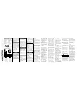
3. If adjustment is required, remove the top cover of
the transceiver to access the RF board. Then manu-
ally adjust the variable capacitor in reference
oscillator U806 for the displayed frequency ±100
Hz (see Figure 4-4). This also sets the receive
frequency.
4. The VCO control line voltage can be checked for the
indicated readings at the junction of R848 and C836.
If it is not within the indicated limits, there may be
a synthesizer problem or the VCO may be defective.
The control voltage is not adjustable.
4.4 TRANSMIT MODULATION
Transmit modulation is set by balancing the
modulation produced by 80 Hz and 3 kHz tones and
then setting modulation limiting using a 1 kHz tone.
All of these tones are internally generated by the trans-
ceiver, so no external audio generator is required.
Proceed as follows:
1. Connect a 50-ohm load to the antenna jack and
monitor the transmit signal with a communication
monitor. Manually or automatically select “Tx
Modulation”.
2. Set the communication monitor for the displayed
frequency and then click “OK” to transmit a signal
modulated with an 80 Hz tone. Enter the measured
deviation (in hertz) in the displayed box and click
“OK”.
3. Continue following the screen instructions to adjust
the 3 kHz tone deviation. The + and – buttons are
clicked to set the deviation to the indicated level.
The 1 kHz tone is then adjusted.
4. The preceding 3 kHz and 1 kHz tone adjustments
are then repeated on several frequencies across the
band. After the last adjustment is made, the trans-
mitter unkeys and the settings are stored.
Figure 4-4 Alignment Points Diagram
J201
L218
Ref Osc Freq.
L215
L213
Pin 20 Pin 19
R848/C836