background image

12

User Manual EE371 Compact Dew Point Senor

Adjustment

The adjustment improves the measurement accuracy of a device. The specimen is compared with the 

reference and brought in line with it. An adjustment can be followed by a calibration which documents 

the accuracy of the adjusted specimen.

The dew point temperature adjustment of EE371 can be performed with the free EE-PCS Product 

Configuration Software, free download at www.epluse.com/configurator.

7.3  Dew Point Adjustment by the User

Dew point adjustment by the user is possible only at low dew points. The adjustment can only be 

carried out if the difference between the ambient temperature and the reference dew point temperature 

is <-60 °C.

Example:

Ambient temperature = 20 °C

Reference dew point temperature must be lower than -40 °C.

8  Maintenance

8.1  Cleaning the Sensing Element

Caution:


ƒ

Never touch the sensing elements.


ƒ

Any attempt to clean the sensing elements mechanically such as rubbing or brushing leads certainly 

to their irreversible damage.

Please refer to the “Cleaning Instructions”, available online at the E+E Download-Center.

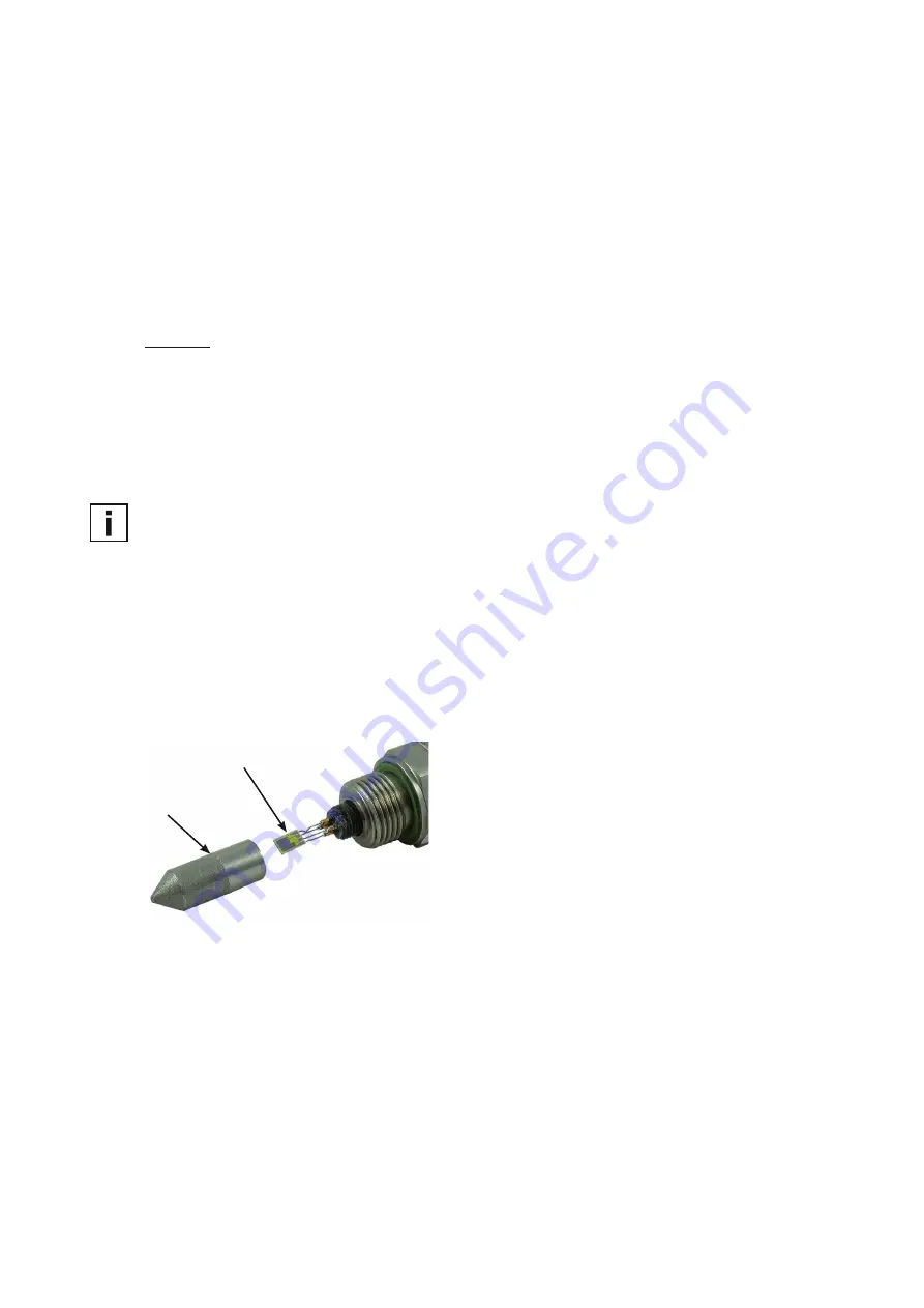
8.2  Filter Replacement

A contaminated filter cap should replaced by a new one. The order number for a new filter is HA010103.

When replacing the filter, please note the following:


ƒ

Unscrew the filter cap very carefully to avoid damaging the sensing element.


ƒ

Handling the filter might clog the pores. Use gloves to screw on the new filter.

Filter cap

Sensing element

Fig. 8 

EE371 filter and sensing elementr

8.3  Self-Diagnosis and Error Messages

Self-diagnosis via LED on the circuit board:
Power LED (green):


ƒ

flashing   

   EE371 is correctly powered / the microprocessor is active


ƒ

constantly lit   

   Electronics defect => please contact the producer

LED D1 (blue):


ƒ

flashing  

   The sensing element is wet (condensation)


ƒ

constantly lit  

   The sensing element is damaged

Self-diagnostic via display (option):


ƒ

Error 1  

   The dew point sensing element is damaged


ƒ

Error 2  

   The sensing element is wet (condensation)


ƒ

Error 3  

   The temperature sensing element is damaged


ƒ

Error 4  

   Short circuit on the temperature sensing element

Summary of Contents for EE371

Page 1: ...BA_EE371 v2 1 Modification rights reserved User Manual EE371 Compact Dew Point Sensor...

Page 2: ...equipment has been tested and found to comply with the limits for a Class A digital device pursuant to part 15 of the FCC Rules These limits are designed to provide reasonable protection against harmf...

Page 3: ...7 4 1 Installation Location 7 4 2 Installing Directly into the Process 8 4 3 Mounting with a Sampling Cell 8 4 3 1 Basic Sampling Cell 9 4 3 2 Sampling Cell with Quick Connector 9 5 Electrical Connec...

Page 4: ...ice 1 2 Safety Instructions 1 2 1 General Safety Instructions Avoid any unnecessary mechanical stress and inappropriate use When replacing the filter cap make sure not to touch the sensing elements Th...

Page 5: ...not put damaged products into operation and protect them from accidental commissioning Mark the damaged product as defective A faulty device may only be investigated and possibly repaired by qualifie...

Page 6: ...power on This advanced auto calibration mechanism takes a little bit longer than the regular auto calibration and is performed up to 5 times during the first hour of operation During auto calibration...

Page 7: ...should be paid to the fact that changes in the pressure of a gas also changes the dew point If there is a pressure difference between the location of installation and the process the measurement can b...

Page 8: ...too high Sensor shall be protected against contamination Removing the sensor must not interrupt the process To obtain a representative sample of the process gas and to avoid measuring errors please no...

Page 9: ...sic Sampling Cell Pressure range 0 64 bar 0 928 psi Order code HA050103 ISO HA050105 NPT 1 2 3 ISO NPT 1 G 1 2 1 2 2 G 1 4 1 4 3 G 1 4 1 4 Fig 6 Basic sampling cell 4 3 2 Sampling Cell with Quick Conn...

Page 10: ...C V mA V mA 10 30V DC 1 7 6 5 2 3 4 1 V 2 GND 3 NC11 4 NC12 5 NC21 6 NC22 7 not connected 10 30V DC Analogue output The switching thresholds are factory set 6 Operating Components 6 1 Electronics Boar...

Page 11: ...EE PCS Product Configuration Software and the optional RS232 interface cable order code HA010304 or with the EE PCA Product Configuration Adapter and the according connection cable order code HA011063...

Page 12: ...ch as rubbing or brushing leads certainly to their irreversible damage Please refer to the Cleaning Instructions available online at the E E Download Center 8 2 Filter Replacement A contaminated filte...

Page 13: ...e and scaleable 0 10 V 0 mA IL 1 mA analogue outputs for Td Tf Wv 4 20 mA 3 wire RL 500 Ohm RL load resistance General Power supply class III 2 15 30 V DC Current consumption typ voltage output 40 mA...

Page 14: ...92310 S vres Tel 33 4 74 72 35 82 E mail info epluse fr E E Elektronik Germany Sch ne Aussicht 8 C 61348 Bad Homburg Tel 49 6172 13881 0 E mail info epluse de E E Elektronik Italy Via Alghero 17 19 20...

Reviews: