background image

5. In-wall Speaker Installation

To install a Studio Series in-wall speaker, proceed as described in 
the following paragraphs and accompanying diagrams:

• 

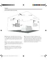
Having selected the installation position and checked for the 
presence of studs (joists), pipe work, ducts or cables, mark 
a portrait orientation cut-line on the wall using the supplied 
template. Check that the dimensions of the cut-line are 
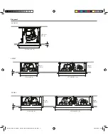
correct: 175 x 275 mm (6

7

8

 x 10

13

16

 in) for the S4-W65  

and 215 x 370 mm (8

1

2

 x 14

9

16

 in) for the S4-W80.

Note: 

Studio Series in-wall speakers are intended to be used in 

portrait orientation.

Use an appropriate tool to cut along the cut-line to create a 
cut-out in the wall. Trial fit the speaker Installation Frame in 
the cut-out to check clearances.

Note:

 In order to reduce the possibility of audible wall vibration 

it may be prudent to apply a bead of adhesive mastic between 
the wall studs and the drywall (plasterboard) in the vicinity of wall 
speakers.

With the cut-out checked, the Installation Frame can be 
installed. Insert the frame into place and while holding it 
against the wall with one hand use the other hand to turn 
and slide the four yellow securing clamps outwards and 
slide them down against the inner surface of the drywall 
(plasterboard).

Note:

 If speaker cables are not already installed it should be done 

at this stage. It is possible that access will be required through the 
opposite side of the wall to route the cables. Use low resistance 
speaker cable with clear polarity marking on its insulation. Low 
resistance is especially important if the length of cable from 
amplifier to speaker exceeds 5 m. Your local Dynaudio retailer or 
distributor will be able to offer advice on speaker cable selection if 
required.

• 

Pull the speaker cable through the Installation Frame and 
wall cut-out. The length of free cable should be sufficient 
to allow the Speaker Unit to be held in one hand while 
connecting the cable to the Speaker Unit terminals with the 
other hand.

The speaker cable can now be connected to the speaker. 
Strip 15 mm insulation from the cable (if necessary), twist 
the wire strands and insert the stripped ends into the 

1

2

3

4

speaker spring terminals. Ensure that the positive conductor 
is connected to the red speaker terminal and the negative 
conductor is connected to the black speaker terminal.

With the Speaker Unit connected to the speaker cable it 
can be inserted into the Installation Frame. Turn the locking 
tabs on the front surface of the Speaker Unit fully clockwise 
(aligned with the lock icons) and insert it in the Installation 
Frame. Push gently around each locking tab until a click is 
heard. The Speaker Unit will then be secured in the frame.

Note:

 Take care that the cable is positioned in such a way that it will 

not get trapped as the Speaker Unit is secured into the Installation 
Frame and is not touching the Speaker Unit in such a manner that it 
is likely to result in audible vibrations.

Note: 

To remove the Speaker Unit from the Installation Frame turn 

the locking tabs 90° counter-clockwise. Take care to support the 
speaker as the locking tabs are turned.

Note:

 Studio Series wall speakers are intended to be installed with 

the tweeter above the bass/mid driver.

The high frequency tonal balance of the Studio Series 
speakers can be adjusted to suit different installation 
environments. A tweeter level switch located on the Speaker 
Unit front panel 3 dB, 0 dB and -3 dB options. 
The level adjustment operates from approximately 3 kHz 
upwards.

Note:

 The +3 dB tweeter level option may be appropriate if, for 

example, carpets, soft furnishings and curtains dominate in the 
listening environment. Alternatively the -3 dB option may be more 
suited to an environment where hard floors and glass predominate. 
In more balanced acoustic environments, the 0 dB option is likely to 
be most appropriate.

• 

With the speaker connected and secured into the Installation 
Frame, in-wall speaker installation is completed by fitting 
the grille. The grille is secured magnetically and requires no 
more than placing into position.

Note: 

If the wall is to be painted following speaker installation, the 

supplied paint mask must be used to protect the speaker hardware 
from paint ingress. Speaker grilles should not be fitted during 
painting. They should be painted separately.

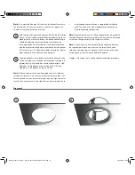
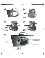
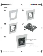
Diagram 6 illustrates the in-wall speaker installation procedure.

5

5

2018 Dynaudio CI manual - Item No. 307001016932 Rev N - EN.indd   14

05/01/2018   12.39

Summary of Contents for S4-C80

Page 1: ...S4 DVC65 S4 C65 S4 C80 S4 W65 S4 W80 Installation Manual Studio Series 2018 Dynaudio CI manual Item No 307001016932 Rev N EN indd 1 05 01 2018 12 39 ...

Page 2: ... damages to any other equipment or other items at the site of use or any other damages whether incidental consequential or otherwise Dynaudio shall not be liable for any anticipated profits any incidental or consequential damages loss of time or other losses incurred by the purchaser in connection with the purchase operation or use of the product The information this document contains is subject t...

Page 3: ...es sources de chaleur radiateurs bouches de chaleur fours et autres y compris les amplifcateurs 9 Utilisez uniquement les câbles accessoires recommandés par le fabricant 10 Confez toute réparation à un technicien qualifé Studio Series speakers are uniquely simple to install Once a ceiling or wall cut out is created no tools are required and installation can be completed by one person without assis...

Page 4: ...ment pack A typical carton contents is illustrated in Diagram 1 Diagram 1 Speaker Unit Grille Cut out Template Installation Frame Paint Mask Document Pack Ø210mm 8 1 4 S4 C65 Note Diagram illustrates in ceiling speaker pack contents In wall pack contents are equivalent Note Square grilles are optionally available for Studio Series in ceiling speakers Contact Dynaudio directly or your local retaile...

Page 5: ...17 16 in max 5 16 in min S4 DVC65 210 mm 167 mm X 48 5 mm max 7 5 mm min 81 4 in 69 16 in 17 8 in max 5 16 in min S4 C80 260 mm 163 mm X 45 0 mm max 7 5 mm min 101 4 in 67 16 in 13 4 in max 5 16 in min S4 W65 175 mm x 275 mm 90 mm X 33 0 mm max 8 5 mm min 67 8 x 10¹³ 16 in 39 16 in 15 16 in max 3 8 in min S4 W80 215 mm x 370 mm 99 mm X 35 5 max 8 8 mm min 81 2 x 149 16 in 37 8 in 13 8 in max 3 8 i...

Page 6: ... 275 mm 1013 16 in 90 mm 3 54 in X 215 mm 81 2 in 99 mm 3 90 in 99 mm 3 90 in S4 W80 370 mm 149 16 in X 168 2 mm 6 62 in S4 DVC65 Ø 210 mm 81 4 in X Diagram 2 2018 Dynaudio CI manual Item No 307001016932 Rev N EN indd 6 05 01 2018 12 39 ...

Page 7: ... be constructed on site In either case Studio Series speakers require a 22 Litre 0 8 ft3 minimum back box volume in order to reach their full audio performance potential Before commencing any Studio Series installation you must be sure that the wall and ceiling positions chosen are free of obstructions such as pipe work ducting or wiring that might interfere with the installation Stud finding pipe...

Page 8: ...audio reproduction they should ideally be located between 3 m 10 ft and 5 m 16 5 ft apart and a similar distance from listening area Note The S4 DVC65 in ceiling speaker can also be used to reproduce stereo audio thanks to its twin tweeter and dual voice coil format Single S4 DVC65 units are however unable to create conventional stereo images In wall Speakers If a pair of Studio Series in wall spe...

Page 9: ...screen with each one approximately 0 5 m 20 in away The centre channel speaker should be located either directly above or below the screen or in the case of an acoustically transparent screen directly behind it In ceiling and In wall Speakers Surround channels Surround channel speakers should be located as close as possible to the requirements of the specific multi channel format usually just behi...

Page 10: ...rotating the Speaker Unit within its Installation Frame and adjusting the tweeter tilt See Section 4 1 for more Note Studio Series in ceiling and in wall speakers are fully appropriate for use in 5 1 2 7 1 2 9 1 2 multi channel systems Studio Series in ceiling speakers are suitable for use in Dolby Atmos installations Note The nature of the installation of in ceiling and in wall speakers means tha...

Page 11: ...nnecting the cable to the Speaker Unit terminals with the other hand 1 2 3 The speaker cable can now be connected to the Speaker Unit Strip 15 mm insulation from the cable if necessary twist the wire strands and insert the stripped ends into the appropriate speaker spring terminals If the ceiling speaker is a S4 C65 or S4 C80 model simply ensure that the positive conductor is connected to the red ...

Page 12: ...S4 C65 or S4 C80 and 0 dB dB or 3 dB options on the S4 DVC65 Note Different tweeter levels may be appropriate to suit different listening environments An environment dominated by carpets soft furnishings and curtains for example might require a higher tweeter level than an environment where tiled floors and glass predominate 5 5 In ceiling speaker installation is completed by fitting the grille Th...

Page 13: ...Tilt to adjust tweeter directivity Rotate speaker to adjust bass mid driver directivity Switch to adjust tweeter level S4 DVC65 Normal Mode S4 DVC65 Dipole Mode S4 C65 C80 Mode switch Dipole selected Mode switch Normal selected 2018 Dynaudio CI manual Item No 307001016932 Rev N EN indd 13 05 01 2018 12 39 ...

Page 14: ...ed ends into the 1 2 3 4 speaker spring terminals Ensure that the positive conductor is connected to the red speaker terminal and the negative conductor is connected to the black speaker terminal With the Speaker Unit connected to the speaker cable it can be inserted into the Installation Frame Turn the locking tabs on the front surface of the Speaker Unit fully clockwise aligned with the lock ico...

Page 15: ... 1 3 4 2 5 Push to click Four locations Rotate clockwise to lock Rotate counter clockwise to release Switch to adjust tweeter level 2018 Dynaudio CI manual Item No 307001016932 Rev N EN indd 15 05 01 2018 12 39 ...

Page 16: ...eeter level options 3 dB 0 dB 3 dB 0 dB 3 dB 3 dB 0 dB 3 dB 3 dB 0 dB 3 dB 3 dB 0 dB 3 dB Tweeter orientation Three tilt angles Three tilt angles Three tilt angles N A N A Bass mid orientation 18 x 360 18 x 360 18 x 360 N A N A Dimensions Depth Ø 232 mm 155 mm Ø 91 8 in 61 8 in Ø 232 mm 167 mm Ø 91 8 in 65 8 in Ø 280 mm 163 mm Ø 11 in 67 16 in 198 x 296 mm 90 mm 73 4 x 1111 16 in 39 16 in 237 x 39...

Reviews: