background image

DS32CR \DS42CR \DS46CR \DS46LX \DS55LX Series

21

EXIT

MENU

:SEL

+-:ADJ

:RETURN

:EXIT MENU

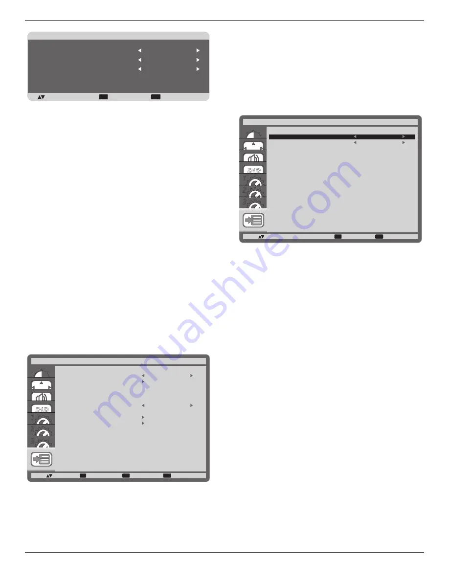
SCREEN SAVER

COOLING FAN

BRIGHTNESS
MOTION

AUTO

OFF
OFF

• 

{

COOLING FAN

} - Select {

ON

} to turn on the cooling fan 

all the time. Select {

AUTO

} to turn on/off the cooling fan 

according to the display’s temperature.
NOTES: 

• 

The default {

AUTO

} option will start running the cooling 

fan if the temperature of 

65°C

 (

152°F

) is reached, and 

will keep running for 

30

 minutes after cooling down to the 

temperature of 

62°C

 (

144°F

).

• 

A temperature-warning message will be shown on the 

screen once the temperature reaches 

79°C

. All key 

function except [

Power

] key will then be disabled. 

• 

{

BRIGHTNESS

} - Select {

ON

} and the brightness of 

the image will be reduced to an appropriate level, and 

the Brightness setting in the Picture menu will become 

unavailable.

• 

{

MOTION

} - Select the time interval ({

10 ~ 900

} Seconds / 

{

OFF

}) for the display to slightly expand the image size and 

shift the position of pixels in four directions (up, down, left, or 

right).

SIDE BORDER COLOR

Adjust the brightness of the black areas displayed on both sides 

of 4:3 images.

CONFIGURATION3 RESET

Reset all settings in the 

CONFIGURATION3

 menu to factory 

preset values.

4.2.8.  ADVANCED OPTION menu

PIP

1
2
3

SET

EXIT

MENU

:SEL

:NEXT

INPUT CHANGE

TERMINAL SETTING

SCAN CONVERSION

COLOR SYSTEM

SCAN MODE

SERIAL CONTROL

LAN SETTING

ADVANCED OPTION RESET

FACTORY RESET

ADVANCED OPTION

:RETURN

:EXIT MENU

NORMAL

LAN

INPUT CHANGE

Select the time for input switching as {

NORMAL

} or {

QUICK

}.

NOTE:   The selection {

QUICK

} may cause a slight noise.

TERMINAL SETTING

Select the mode to display the HDMI or DVI signal according to 

their signal format depending on their source device.

• 

{

DVI MODE

}: Used for DVI-D signal.

• 

Select {

DVI-PC

} when the source device is a PC.

• 

Select {

DVI-HD

} when the source device is a video 

device.

• 

{

HDMI SIGNAL

}: Used for HDMI signal.

• 

Select {

LIMITED

} when displaying the signal that uses 

16 to 235 levels of 256 levels for each R, G, and B.

• 

Select {

FULL

} when displaying the signal that uses all 

256 levels (from level 0 to 255).

PIP

1
2
3

EXIT

MENU

:SEL

+-:ADJ

DVI-MODE

HDMI SIGNAL

TERMINAL SETTING

:RETURN

:EXIT MENU

DVI-PC

FULL

SCAN CONVERSION

Choose to enable or disable the IP (Interlace to Progressive) 

conversion function.

• 

{

PROGRESSIVE

} - Enable the IP conversion function 

(recommended). Once enabled, the interlace input signal will 

be converted to progressive format for better display quality.

• 

{

INTERLACE

} - Disable the IP function. This mode is 

suitable for displaying motion pictures, but it increases the 

chance of image retention.

COLOR SYSTEM

Selects the Color System depends on your input video format.
The options are: {

AUTO

} / {

NTSC

} / {

PAL

} / {

SECAM

} / 

{

4.43NTSC

} / {

PAL-60

}.

NOTE:   This item is functional for 

S-VIDEO

 or

 VIDEO

 input 

only.

SCAN MODE

Change the display area of the image.

• 

{

OVERSCAN

} - Display about 95% of the original size of the 

image. The rest of the areas surrounding the image will be 

cut off.

• 

{

UNDERSCAN

} - Display the image in its original size.

NOTE:   This item is functional for 

HDMI

-Video timing input 

only.

SERIAL CONTROL

Select the nectwork control port.
The options are: {

RS-232C

} / {

LAN

}.

NOTE:   If  {

LAN

} is selected, then {

RS-232C

} will not be 

activated, even if a cable is attached, and vice versa.

LAN SETTING

Assign {

IP ADDRESS

}, {

SUBNET MASK

}, and {

DEFAULT 

GATEWAY

} for the display.

Summary of Contents for DS32CR

Page 1: ...ssional LCDs Version 4 00 The use of diagrams and illustrations in the manual for reference only actual product may be different Product design and specifications are subject to change without notice...

Page 2: ...DS32CR DS42CR DS46CR DS46LX DS55LX Series ii...

Page 3: ...nherent in the LCD technology In most cases the afterimage will disappear gradually over a period of time after the power has been switched off Be aware that the after image symptom cannot be repaired...

Page 4: ...requirement of Information Technology Equipment EN55022 2006 A1 2007 Radio Disturbance requirement of Information Technology Equipment EN55024 1998 A1 2001 A2 2003 Immunity requirement of Information...

Page 5: ...ake certain that the cord grip is clamped over the sheath of the lead not simply over the three wires WARNING THIS APPLIANCE MUST BE EARTHED Important This apparatus is supplied with an approved mould...

Page 6: ...DS32CR DS42CR DS46CR DS46LX DS55LX Series vi China RoHS RoHS Pb Hg Cd Cr 6 PBB PBDE O O O O O O X X O O O O X O O O O O X O O O O O X O O O O O O SJ T11363 2006 X SJ T11363 2006 10 2000m...

Page 7: ...nsumer Education Initiative Waste Electrical and Electronie Equipment WEEE Attention users in European Union private households This marking on the product or on its packaging illustrates that under E...

Page 8: ...itch Cover 9 3 2 Connecting External Equipment DVD VCR VCD 10 3 2 1 Using COMPONENT video input 10 3 2 2 Using HDMI video input 10 3 3 Connecting a PC 11 3 3 1 Using VGA input 11 3 3 2 Using DVI input...

Page 9: ...s ix 4 2 5 CONFIGURATION1 menu 18 4 2 6 CONFIGURATION2 menu 19 4 2 7 CONFIGURATION3 menu 20 4 2 8 ADVANCED OPTION menu 21 5 Input Mode 23 6 Cleaning and Troubleshooting 24 6 1 Cleaning 24 6 2 Troubles...

Page 10: ...itch cover Remote Control and AAA Batteries Screw for Power switch cover M3 x 8 x 1 Video Signal Cable D SUB to D SUB Cable NOTES Please make sure that for all other regions apply a power cord that co...

Page 11: ...he display face down on the protective sheet 4 After inserting the stand in the guide block tighten the screws on both sides of the display NOTE The long end side of the stand should face to the front...

Page 12: ...n a safe place for reuse 1 5 Mounting on a Wall To mount this display to a wall you will have to obtain a standard wall mounting kit commercially available We recommend using a mounting interface that...

Page 13: ...ll mounting kit use M6 mounting screws having a length 10 mm longer than the thickness of the mounting bracket and tighten them securely Caution To prevent the display from falling For wall or ceiling...

Page 14: ...adjust the selected item while OSD menu is on 7 button Move the highlight bar down to adjust the selected item while OSD menu is on 8 MENU button Return to previous menu while OSD menu is on or to act...

Page 15: ...HDMI output of an AV device by using a DVI HDMI cable 7 HDMI IN Connect the HDMI output of an AV device or the DVI D output of a PC by using a DVI HDMI cable 8 VGA IN D Sub Connect the computer VGA ou...

Page 16: ...te the setting inside the OSD menu 8 AUTO ADJUST button Press to run the Auto Adjust function NOTE This button is functional for VGA input only 9 MUTE button Press to turn the mute function on off 10...

Page 17: ...ntrol for a long period remove the batteries 2 3 3 Handling the remote control Do not subject to strong shock Do not allow water or other liquid to splash the remote control If the remote control gets...

Page 18: ...he power switch is provided to prevent the display from being turned on or off accidentally To lock the cover into position 1 Align and insert the cover to the indentation located beside the main swit...

Page 19: ...Series 10 3 2 Connecting External Equipment DVD VCR VCD 3 2 1 Using COMPONENT video input Audio Output To AUDIO IN 2 3 DVD VCR VCD COMPONENT YPbPr COMPONENT YPbPr 3 2 2 Using HDMI video input DVD VCR...

Page 20: ...onnecting a PC 3 3 1 Using VGA input To VGA IN PC or IBM compatible From analog VGA output Mini D Sub 15 pin From audio output To AUDIO IN 1 2 3 3 3 2 Using DVI input From audio output To DVI IN PC or...

Page 21: ...DS32CR DS42CR DS46CR DS46LX DS55LX Series 12 3 3 3 Using HDMI input To HDMI IN PC or IBM compatible From HDMI output...

Page 22: ...DS42CR DS46CR DS46LX DS55LX Series 13 3 4 External Audio Connection 3 4 1 Connecting external speakers External speaker 3 4 2 Connecting an external audio device Stereo Amplifier RCA Audio In To AUDI...

Page 23: ...of display 2 Connect the VGA OUT connector of display 1 to the VGA IN connector of display 2 Connect the VIDEO OUT connector of display 1 to the VIDEO IN connector of display 2 To RS 232C IN RS 232C C...

Page 24: ...SET EXIT MENU SEL NEXT BRIGHTNESS CONTRAST SHARPNESS BLACK LEVEL TINT COLOR COLOR TEMPERATURE USER COLOR GAMMA SELECTION NATIVE NATIVE NOISE REDUCTION FILM MODE PICTURE RESET PICTURE RETURN EXIT MENU...

Page 25: ...to let the display detect and display available signal sources automatically ON Set the display to display the image automatically once a signal is connected OFF Once a signal is connected it can only...

Page 26: ...t all settings in the AUDIO menu to factory preset values 4 2 4 PIP menu PIP 1 2 3 SET EXIT MENU PIP SEL NEXT PIP MODE PIP SIZE PIP AUDIO PIP H POSITION PIP V POSITION SUB INPUT PIP RESET PIP RETURN E...

Page 27: ...OFF INPUT WED SAT MON THU SUN TUE FRI EVERY WEEK 2 Press or button to select a schedule item item number 1 7 and then press SET button to mark it the item number EXIT MENU SEL RETURN EXIT MENU SCHEDU...

Page 28: ...the OSD menu INFORMATION OSD Set the period of time the information OSD displayed on the upper right corner of the screen The information OSD will display when input signal is changed The information...

Page 29: ...ation related to the primary audio is displayed without sync CC3 Captions are displayed in sync with the secondary audio CC4 Information related to the secondary audio is displayed without sync TT1 TT...

Page 30: ...t noise TERMINAL SETTING Select the mode to display the HDMI or DVI signal according to their signal format depending on their source device DVI MODE Used for DVI D signal Select DVI PC when the sourc...

Page 31: ...values ADVANCED OPTION RESET Reset all settings in the ADVANCED OPTION menu to factory preset values 1 Press SET button to enter the submenu 2 Press or button to select YES and then press SET button...

Page 32: ...tandard 576p 50 Hz 27 MHz HDTV Resolution Standard Resolution Active Resolution Refresh Rate Pixel Rate Aspect Ratio Stand for Mode H Pixels V Lines 720p 1280 720 50 Hz 74 25 MHz 16 9 Normally DVB Mod...

Page 33: ...loth or a soft lint free cloth If the surface becomes dirty soak a soft lint free cloth in a mild detergent solution Wring the cloth to remove excess liquid Wipe the surface of the display to remove d...

Page 34: ...e screen The zoom mode is not correctly set Use the Zoom mode or Custom zoom function in the Screen menu to fine tune display geometry and time frequency parameter Can hear sound but no picture Improp...

Page 35: ...1 Type A 18 pin Digital RGB TMDS Video Audio MAX Video 720p 1080p 1920 x 1080 60 Hz WUXGA Audio 48 KHz 2 Channel L R Supports LPCM only DVI D Input DVI D jack Digital RGB TMDS Video VGA Input D Sub J...

Page 36: ...pecifications Temperature Operational 0 40 C Storage 20 60 C Humidity Operational 20 80 RH No condensation Storage 5 95 RH No condensation Altitude Operational 0 3 000 m Storage Shipment 0 9 000 m Int...

Page 37: ...x 1080 60 Hz WUXGA Audio 48 KHz 2 Channel L R Supports LPCM only DVI D Input DVI D jack Digital RGB TMDS Video VGA Input D Sub Jack x 1 15 pin Analog RGB 0 7V p p 75 H CS V TTL 2 2k SOG 1V p p 75 MAX...

Page 38: ...ure Operational 0 40 C Storage 20 60 C Humidity Operational 20 80 RH No condensation Storage 5 95 RH No condensation Altitude Operational 0 3 000 m Internal Speaker Item Specifications Type 1 Way 1 Sp...

Page 39: ...1080 60 Hz WUXGA Audio 48 KHz 2 Channel L R Supports LPCM only DVI D Input DVI D jack Digital RGB TMDS Video VGA Input D Sub Jack x 1 15 pin Analog RGB 0 7V p p 75 H CS V TTL 2 2k SOG 1V p p 75 MAX 72...

Page 40: ...ure Operational 0 40 C Storage 20 60 C Humidity Operational 20 80 RH No condensation Storage 5 95 RH No condensation Altitude Operational 0 3 000 m Internal Speaker Item Specifications Type 1 Way 1 Sp...

Page 41: ...WUXGA Audio 48 KHz 2 Channel L R Supports LPCM only DVI D Input DVI D jack Digital RGB TMDS Video VGA Input D Sub Jack x 1 15 pin Analog RGB 0 7V p p 75 H CS V TTL 2 2k SOG 1V p p 75 MAX 720p 1080p 1...

Page 42: ...ty Operational 20 80 RH No condensation Storage 5 95 RH No condensation Altitude Operational 0 3 000 m Internal Speaker Item Specifications Type 1 Way 1 Speaker Input 10 W RMS Impedance 8 Output Sound...

Page 43: ...ports LPCM only DVI D Input DVI D jack Digital RGB TMDS Video VGA Input D Sub Jack x 1 15 pin Analog RGB 0 7V p p 75 H CS V TTL 2 2k SOG 1V p p 75 MAX 720p 1080p 1920 x 1080 60 Hz WUXGA VGA Output D S...

Page 44: ...ty Operational 20 80 RH No condensation Storage 5 95 RH No condensation Altitude Operational 0 3 000 m Internal Speaker Item Specifications Type 1 Way 1 Speaker Input 10 W RMS Impedance 8 Output Sound...

Page 45: ...DS32CR DS42CR DS46CR DS46LX DS55LX Series 36 2012 All rights reserved Specifications are subject to change without notice...

Page 46: ...DS32CR DS42CR DS46CR DS46LX DS55LX Series 37...

Reviews: