


Note: If you will be entering your Chipmunk in
IMAA events you need to review their
requirements for servo and control linkage
sizes. They require high-torque servos on
control surfaces and 4-40 size control linkages,
with metal clevises.
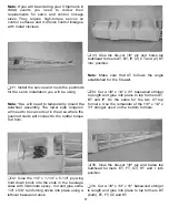
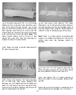
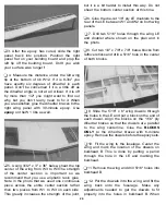
Q 33, Glue the die-cut 1/8" ply and balsa top
bulkhead formers AT, BT, IP, (2) CT and (2) DT
into position.
Note: Make sure that AT follows the angle
established for the firewall.
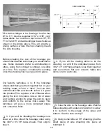
Q 31. Install the servos and route the pushrods
for the servo installation you will be using.
Note: You will need to temporarily mount the
tailwheel assembly. The lower side longeron
will need to be carved out in the area where the
pushrod clevis will connect to the rudder torque
rod horn.
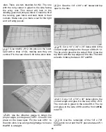
Q 34. Cut a 1/8" x 1/4" x 31" basswood stringer
to length and glue into place to top formers AT,
BT and IP. Do the same for the two CT top
formers. Use the remainder of the 1/8" x 1/4" x
31" stringer used on the bottom formers.
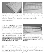
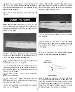
Q 35. Glue the die-cut 1/8" piy and balsa top
bulkhead formers ET, FT, GT, HT and I into
position.
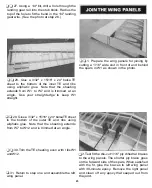
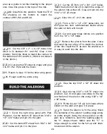
Q 32. Glue the 1/4" x 1-1/4" x 5-1/4" ply wing
hold down block into the slots in the fuselage
sides with 30-minute epoxy. Cut and glue some
1/4" x 3/8" reinforcing sticks into place using a
leftover basswood stick.
Q 36. Cut a 1/8" x 1/4" x 31" basswood stringer
to length and glue into place to top formers DT
(both), ET, FT, GT and HT.
17


