Dyn'Aéro MCR ULC ECOLIGHT HB-WAZ, Aircraft Flight Manual
The Dyn'Aéro MCR ULC ECOLIGHT HB-WAZ Aircraft Flight Manual is an essential resource for pilots seeking valuable information on operating this remarkable aircraft. Available for download, this comprehensive manual ensures a safe and efficient flight experience. Obtain your free copy today from our website and unlock the full potential of this exceptional product.
Share
Download


Reviews:
No comments
Related manuals for MCR ULC ECOLIGHT HB-WAZ

RX1000
Brand: Rapid Pages: 93

R1600
Brand: Rapid Pages: 140

BT-CK 18 2B-1.5 Kit
Brand: Taurus Pages: 40

MAG-8200 Series
Brand: Magna-Matic Pages: 10

7064216
Brand: Batavia Pages: 46

KEN-503-1550K
Brand: Kennedy Pages: 2
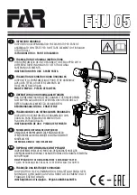
FHU 05
Brand: FAR Pages: 52

1946C4,8
Brand: Beta Pages: 76

JS800
Brand: jcb Pages: 19

12168201001
Brand: Rehau Pages: 72

WIG 4
Brand: Kaindl Pages: 10

2305570-1
Brand: TE Pages: 6

HFS27-300
Brand: Fein Pages: 77

5050731100
Brand: molex Pages: 13

SAGOLA Junior G
Brand: Elcometer Pages: 20

P635B
Brand: Senco Pages: 11

DG83231
Brand: STM Pages: 3

YT-82055
Brand: YATO Pages: 112


