background image

Model XE569s

Work

Disassembling and assembling
of parts

Parts 

10. 

Rail 

Base 

Assembly

Ver.

1

2

3

4

Steps

1.

Adjust the 

incline 

position 

to 

level 3 

and 

use

Phillips 

head 

screwdriver to 

release 

two

M5x15m

screws 

for the 

incline 

bottom

cover and rem

ove it, as shown in figure 1.

2.

Use two 14 m

/m 

wrenches and 12 m

/m

wrench 

to 

release 

3/8

"x1-1/2"

 hex head

bolts,  

3/8

"x19x1.5T

flat 

washers, 

3/8x7T

nyloc 

nuts, 

5/16x2-1/4 

hex 

head 

bolt,

5/16

"x1.5T

 split washer, 5/16

"x20x1.5T

flat

washer and 5/16 

star washer, which 

secure

the 

Inclinable 

Rail Assem

bly, and 

takeit

apart, as 

shown 

in 

figures 

2&.3.

3. Reverse above steps to resum

e all

parts.

Summary of Contents for XE569s

Page 1: ...dlebar Covers Front Rear Left Pedal Arm Cover Console Left Chain Cover Left Pedal Console Mast Covers L R Rear Bar Cover Slide Wheel Cover Middle Stabilizer Cover Inclinable Rail Cover Connecting Arm Covers L R Incline Cover Pedal Arm Locking Pin Assembly Round Disk Cover Right Pedal Round Disk Incline Bottom Cover Right Chain Cover ...

Page 2: ...le Bar Left Connecting Arm Bushing Housing Left Adjustable Pedal Gear Motor Rail Base Assembly Drive Pulley Inclinable Rail Assembly Right Pedal Arm Outer Adjustment Tube Right Connecting Arm Locking Tube Assembly Inner Adjustment Tube Flywheel Cross Bar Right Adjustable Pedal ...

Page 3: ...ight Chain Covers 7 Cross Bar Assembly 8 Idler Wheel Assembly 9 Flywheel and the Belt 10 Rail Base Assembly 11 Inclinable Rail Assembly II Troubleshooting 1 The Console 2 Left Right Chain Covers and Round Disk 3 The Flywheel 4 The Belt 5 Handlebar Assembly 6 Pedal Arm Assembly 7 Gear Motor III Q A 1 Noises 2 Slippage 3 Resistance and Incline 4 Smoothness 5 Others ...

Page 4: ......

Page 5: ...c o n s o le a ss h o w ninfig 1 2 T h e nd is c o n n e c tth ec o m p u te r c a b le h a n dp u ls ec a b lea n d re s is ta n c ec a b leino rd e rto ta k ea p a rt th ec o n s o le a s s h o w ninfig 2 3 T ore s u m e th e c o n s o le c o n n e c t th e c a b le s re tu rnth e c o n s o le o n to th eC o n s o leM a s ta n ds e c u rew ith fo u r M 5 x 1 0 m mP h illip sh e a d s c re w s ...

Page 6: ... h ic hs e c u rele fta n drig h tc o n n e c tin g a rm c o v e rstota k eo ffth e m a ss h o w nin fig u re 2 3 T h e nu s e1 2 m ma n d1 3 m mw re n c h e sto re le a s e 5 1 6 x 1 1 4 h e x h e a d b o lt 5 1 6 x 2 0 x 1 5 Tfla tw a s h e ra n d5 1 6 x 7 Tn y lo c n u tino rd e rtos e p a ra teH a n d le b a rA s s e m b ly fro m R o dE n dB e a rin g a ss h o w ninfig u re 3 4 U s e1 2 m m w ...

Page 7: ......

Page 8: ...de n d b e a rin g a ss h o w ninfig u re 1 2 U s e1 2 m mw re n c htore le a s e5 1 6 x 1 5 m m h e xh e a db o lta n d5 1 6 x 2 3 fla tw a s h e rfo rth ec o n n e c tin ga rm a n d p u llo u tth ec a rria g eb o lts oth a tth e c o n n e c tin ga rm c a nb eta k e na p a rt a s s h o w ninfig u re 2 3 3 T ore m o v eth ea d ju s ta b lep e d a l o r lo c k in gp in u s eC rin gp lie rsto re m o...

Page 9: ...M 5 x 1 0 m m p h illip sh e a d s c re w sfo rth ep e d a ltota k ea p a rtth e lo c k in gp inb ra c k e t a ss h o w ninfig u re 6 5 U s e P h illip sh e a ds c re w d riv e r to re le a s efo u rM 5 x 1 0 m m p h illip sh e a d s c re w sw h ic hs e c u reth ep e d a ltota k e ita p a rt a ss h o w ninfig u re 7 6 R e v e rs ea b o v es te p store s u m ea ll p a rts ...

Page 10: ...s e3 8 x 2 1 4 s o c k e t h e a dc a pb o lt 3 8 x 1 9 x 1 5 Tfla t w a s h e r a n d3 8 x 1 1 T n y lo cn u t w h ic hs e c u reth ep e d a la rm a n d b u s h in gh o u s in gp e d a la rm a n dta k e a p a rtth e p e d a la rm a ss h o w ninfig u re 2 3 U s e 1 2 m mh e x w re n c h to re le a s e 5 1 6 x 1 5 m m h e x h e a d b o lt a n d 5 1 6 x 3 5 x 1 5 Tfla tw a s h e rfo rth eb u s h in ...

Page 11: ...stota k e a p a rt le ft a n drig h t c o n s o lem a s t c o v e rs a ss h o w ninfig u re 1 3 U s e1 4 m m w re n c htore le a s e3 8 x 3 4 hex head bolt 3 8 x23x2T c u rv e dw a s h e r 3 8 x2 1 4 hex head bolt and 3 8 x2T s p lit w a s h e rfo rth ec o n s o lem a s t a ss h o w nin fig u re s2 3 4 P u llo u tth e c o n s o le m a s tc o m p u te rc a b le 5 R e v e rs ea b o v es te p store s...

Page 12: ... le a s e e ig h t 3 5 x 1 2 m m s h e e tm e ta ls c re w sa n d th re e 5 x 1 6 m m ta p p in gs c re w sw h ic hs e c u reth e rig h tc h a inc o v e r a ss h o w ninfig u re 1a n d2 3 T h e na g a in u s eP h illip sh e a ds c re w d riv e rto re le a s e3 5 x 1 2s h e e tm e ta ls c re w s 1 4 x19 fla tw a s h e rsa n d5 x 1 6m m ta p p in gs c re w s w h ic hs e c u reth erig h tc h a inc o ...

Page 13: ...n c o v e rc a nb e ta k e na p a rt 5 T ore p la c e D C c a b le s ju s tta k e th e n u t o nth ele ftc h a inc o v e rtota k eth e c a b le sa p a rt 6 R e v e rs ea b o v es te p store s u m eb o th c h a in c o v e rs B e s u re to p u t 5 1 6 x2 3 x 1 5 Tfla tw a s h e ro nth ele ftc h a in c o v e r a n dth ec a b le sa refre efro mc h a in c o v e ra n dth ero u n dd is k a ss h o w ninfi...

Page 14: ...s e 5 1 6 x 1 5 m m h e x h e a d b o lt a n d 5 1 6 x 3 5 x 1 5 Tfla t w a s h e r w h ic hs e c u re th e c ro s sb a r R e le a s e fu rth e rM 8 x 3 0 m m s o c k h e a dc a pb o lta n dth ec ro s sb a rc a nb eta k e n a p a rt a ss h o w ninfig u re s1 2 3 3 U s eP h illip sh e a ds c re wd riv e rtore le a s e e ig h t 5 x 1 6 m mta p p in g s c re w s a n d 1 4 x 1 9 x 1 5 Tfla tw a s h e ...

Page 15: ... assembling of parts Parts 7 Cross Bar Ver 5 S te p s 4 T ore s u m eth ec ro s sb a r p u tito nth ec ra n k a x lea n dth e np u tinth ew o o d ru ffk e y w ith ro u n dh e a din s id e a ss h o w ninfig u re5 R e tu rno th e rp a rts ...

Page 16: ...w re n c htore le a s eM 8 x 2 0 c a rria g e b o lt M 8 x 7 T n y lo c n u t a n d 5 1 6 x 2 0 x 1 5 Tfla tw a s h e rtota k ea p a rtth e id le rw h e e l a s s e m b ly a ss h o w ninfig u re s 1 2 3 R e v e rs ea b o v es te p store s u m ep a rtsa n d tig h te nM 8 x 9 Tn y lo cn u to nth eJ b o ltu n til th eb e ltw ithc e rta intig h tn e s s A d ju s tb e lt tig h tn e s su n til th es o u...

Page 17: ... o leth e nre m o v e th e s te e lc a b le a s s h o w ninfig u re 1 3 U s e 1 5 m mw re n c h to re le a s e 3 8 U N F 2 6 x 9 Tn u t w h ic hs e c u re sth e fly w h e e l o nth efra m e a n dre m o v eth e fly w h e e la n dth eb e lt a ss h o w ninfig u re s 2 3 4 R e v e rs ea b o v es te p store s u m eth e fly w h e e la n dth eb e lt M a k es u reth e b e lt isinth em id d leo f th ed riv...

Page 18: ...dre m o v e it a ss h o w ninfig u re 1 2 U s etw o1 4m mw re n c h e sa n d1 2m m w re n c htore le a s e3 8 x1 1 2 h e xh e a d b o lts 3 8 x19x1 5T fla tw a s h e rs 3 8 x 7 T n y lo c n u ts 5 1 6 x 2 1 4h e x h e a db o lt 5 1 6 x1 5T s p litw a s h e r 5 1 6 x20x1 5T fla t w a s h e ra n d 5 1 6s ta rw a s h e r w h ic hs e c u re th eIn c lin a b leR a il A s s e m b ly a n dta k eit a p a ...

Page 19: ... d in c lin e c o v e r a ss h o w ninfig u re s1 2 3 3 U s etw o1 4m m w re n c h e store le a s e 3 8 x2 1 2 h e xh e a db o lt 3 8 x19x1 5T fla tw a s h e ra n d3 8 x7T nyloc nut which secure the inclinable rail assembly and incline motor holder as shown figure 4 4 U s e1 2m m w re n c htore le a s e5 1 6 x 1h e x h e a db o ltsa n d5 1 6 x35x2T fla t w a s h e rs w h ic hs e c u reth ein c lin...

Page 20: ... ra n d in c lin e d e v ic e a ss h o w ninfig u re 6 6 U s e tw o 1 7 m mw re n c h to re le a s e M 1 0 x 1 3 0 m m h e xh e a db o lt 3 8 x19x1 5T flat washer and M10x8T nyloc nut which secure on the incline device and rail base assembly and remove the incline device as shown in figure 7 7 Ifn e c e s s a ry ju s tre le a s eM 5 X 1 5 m m p h illip s h e a ds c re w sa n dy o uc a nta k eo ff ...

Page 21: ...w e rja c k a re p lu g g e dinp ro p e rly a ss h o w ninfig u re 1 2 T h e nm a k es u reth a ta llc a b le sa rec o n n e c te d p ro p e rlyo n toth ec o n s o le a ss h o w ninfig u re 2 3 R e m o v eth ec o n s o lea n dc h a inc o v e rsto c h e c ka ll c a b le sa rec o n n e c te dp ro p e rly M a k es u reth e rea ren oc a b le sd a m a g e d a s s h o w ninfig u re 2 ...

Page 22: ... o thC h a inC o v e rsre fe rrin gtop ro c e d u re 6 3 If n o is e sa rec a u s e db yth es w in gD riv e P u lle y th e nta k e a p a rtb o thC h a inC o v e rsa n d R o u n d D is k a n d u s e P h illip s h e a d s c re w d riv e rtore le a s e5 x 1 6m mta p p in g s c re w sw ith1 4 x 1 9m m fla tw a s h e rs w h ic h a reo nth eR o u n dD is k C h e c kth eR o u n d D is ka n dC ro s sB a r...

Page 23: ...m b le dp ro p e rlyth a tfu rth e rc a u s e s m is a lig n m e n t F o llo w th ep ro c e d u reto re le a s eth eF ly w h e e la n db e lttom a k e a d ju s tm e n t a ss h o w ninfig u re 1 2 If th eF ly w h e e l ism a k in gn o is e s c h e c kif n o is e sa red u etofo re ig n m a te ria lso rru b b in g Ifa d ju s tm e n tis im p o s s ib le re p la c eth eF ly w h e e lw ith an e wo n e a...

Page 24: ...u lle yo r m is a lig n m e n t a m o n gth eb e lt d riv ep u lle ya n dth efly w h e e l th e n tu rnth e b e ltw ithth es p e e db e tw e e n1 0 0a n d1 2 0 R P Ma n ds to pa b ru p tlytos e eif th e reis a n y th in ga b n o rm a l R e s u m eth ep a rtsifth e re isn o th in gw ro n g 2 Ifth eb e lt d riv ep u lle ya n dth efly w h e e ld o n o ta lig nins tra ig h tlin e a d ju s tth efly w h...

Page 25: ...ra th e r th a nfittin g tig h tlya n das m a lla m o u n to fp la yisn o rm a l H o w e v e r a stim ela s tsth e re m ig h tb en o is e s w h ic ha re c a u s e db yp a rtsw e a rin go u t A p p ly s o m e lu b ric a n t o n th e 1 7 x 2 8 4 L h a n d le b a r s h a ft m a yim p ro v eth en o is e p ro b le m Ifth en o is ec o m e sfro m c ra n ka x le b e a rin g re p la c e 6 0 0 3b e a rin g ...

Page 26: ...ng parts applying some lubricate on parts is also required Lubrication while servicing is highly recommended as shown in figures1 2 It might solve many problems 2 There are many factors which affect the feeling of smoothness The most important key point is to make sure that sliding wheels move parallel and smoothly on the rails In brief Pedal Arm should keep parallel with Connecting Arm and both P...

Page 27: ...p e r c u rv a tu rea n dw ith o u ts lip p in g C h e c kifth e ro de n db e a rin gisd a m a g e do rn o ta n dth e tig h tn e s so fth ero de n db e a rin ga sth e s ea re fa c to rsc a u s in gn o is e s R e p la c eth ero de n d b e a rin gw ith1 9m m w re n c hw h e nn e c e s s a ry a ss h o w ninfig u re 3 4 Generally when servicing the elliptical we start from the Sliding Wheels Try to ch...

Page 28: ...th the resistance check the console and then the gear motor If the gear motor doesn t work it is necessary to check if all the cable is well connected To replace the gear motor if necessary use Phillips head screwdriver to unscrew tapping screws which secure the gear motor as show in figures 1 2 3 4 ...

Page 29: ...b e tw e e n C h a inC o v e rsR o u n dD is k B u s h in gH o u s in g a n dC ro s sB a r B e lta n dD riv eP u lle y Id le r W h e e lA s s e m b ly H a n d le b a ra n dM a s ts h a ft F ly w h e e la n dC a b letoS lid in gW h e e lsa n d R a ilA s s e m b ly e v e nP e d a ls e tc In s u ffic ie n t lu b ric a tio n s m o o th n e s so rlo o s es c re w sa re m a jo rc a u s e s a ss h o w ni...

Page 30: ...cket head cap Bolt on top and the 3 8 x11T nyloc nut on the bottom must be tight Suggested applying torque is between 500 600lbs range as show in figure 2 4 Cross Bar the M8x30m m socket head cap bolt on the cross bar must be tight Suggested applying torque is between 550 600lbs range As show in figure 3 5 B e lt T h isisac o m m o np ro b le m D u etoth e lo n gru n n in gtim e b e ltu s u a llyg...

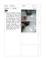
Page 31: ...crews at the loosing parts first If it occurs at the connecting part the reason may be the damages or wears by long time using or incorrect assemble method For example the shaking pedal may occur by incorrect assembling of the carriage bolt The wobble of the whole unit can be solved by adjusting the foot pad screws as shown in figures 1 2 ...

Page 32: ......

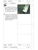
Page 33: ...ightened when there are clicks in the movement or any lack of smooth during the workout 2 If there is any foreign materail or dirt sticking on the sliding wheels sliding rails be sure to remove by wiping with alcohol then applied some lubricant again as shown in the picture Model XE569S Work Q A Problem 5 Other problems Rev ...

Page 34: ......

Reviews: