Model XE569s
Work
Disassembling and assembling of
parts
Parts
2.
Handlebar
Assembly
Ver.
1
2
3
4
Steps
1
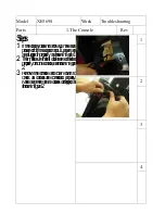
Use
Phillips
head
screwdriver to
release
three
3.5x12m
m
sheet m
etal screws
for
the
front and
rear handlebar cover, as
shown
in
figure
1.
2. Release
two M5x15m
m
Phillips head
screws
and
3.5x12
sheet m
etal screw
which
secure
left and
right connecting
arm
covers to take off them
, as shown in
figure
2.
3.
Then use 12m
/m
and 13m
/m
wrenches to
release
5/16"x1-1/4"
hex
head
bolt,
5/16
"
x20x1.5T
flat
washer
and
5/16"x7T
nyloc
nut in
order to
separate
Handlebar Assem
bly
from
Rod
End
Bearing, as
shown
in
figure
3.
4.
Use
12m
/m
wrench to release
5/16
"
x15
m
m
hex
head
bolt
and
5/16
"
x23x1.5T flat washer to
take
apart
handlebar
assem
bly
from
console
m
ast, as shown in figure
4.
.


