


Modbus
®
Communication Protocol DIP Switch Settings
Use the middle DIP Switch SW2 to configure the Modbus
®
Communication Protocol
address of the device. The LCD will show the address when the transmitter is powered
on. Valid addresses range from 1 to 247. By default, the device is shipped with the
address 127 (as shown in Figure 10). A valid and unused address should be set before
connecting to an existing network. However, the address can be changed while the
device is operational. If the address is changed, the device will stop responding to the
currently configured address immediately. The device waits 15 seconds after the last
switch change before applying the new address. The device will not function properly
if an invalid address is set. The red LED will periodically blink once indicating an invalid
address. The LCD will display
A Err
when the transmitter is powered on if the address
is invalid. See Appendix V for setting the Modbus
®
Communication Protocol address
of the device. Use the right DIP Switch SW3 to configure other hardware and software
options.
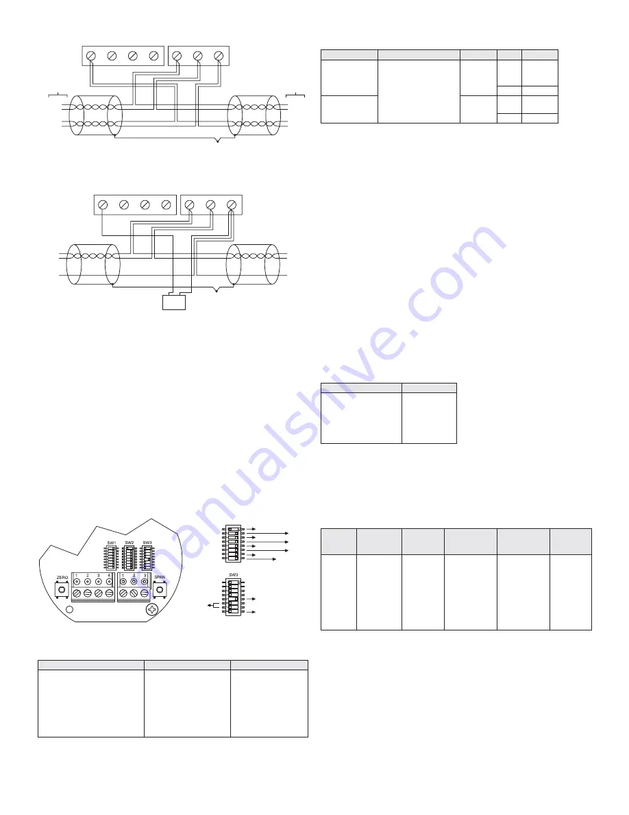
PWR GND IOUT VOUT
TO NEXT
DEVICE
D1(+)
D0(-)
PWR
COM
D1(+)
D0(-)
PWR
COM
TO PREVIOUS
DEVICE
D1(+) D0(-) COM
Figure 7: Common power supply
D1(+)
D0(-)
COM
D1(+)
D0(-)
COM
POWER
SUPPLY
+ -
PWR GND IOUT VOUT D1(+) D0(-) COM
Figure 8: Local power supply
SW2
KEY:
AUTO SERIAL
CONFIGURATION
TERMINATING
RESISTOR
BIAS
RESISTOR
128 - MSB
64
32
16
8
4
2
1 - LSB
Figure 9
Switch
On
Off
1-2 – Display Units Selection
3-4 – Reserved
5 - Intelligent Serial
Configuration
6 – D1(+) Network resistor
7 – D0(-) Network resistor
8 – Terminating resistor
Enabled
511Ω Pull-up to 5V
511Ω Pull-down to GND
120Ω between D0(-) and
D1(+)
Disabled
Pull-up not connected
Pull-down not
connected
Open
Table 5: DIP switch SW3 functions
APPENDIX IV: Programming Via Modbus
®
Communication Protocol
Intelligent Serial Configuration
Intelligent serial configuration enables the device to determine the baud rate, data
size, party, stop bits and even the Modbus
®
Communication Protocol mode directly
from the serial traffic. This allows the Series AVLV to be quickly and easily deployed
after a valid Modbus
®
Communication Protocol address is chosen.
To activate intelligent serial configuration, set a valid Modbus
®
Communication Protocol
address using the left DIP switch SW2, connect the serial bus and power wires, and
then apply power. The device will power up and begin examining the serial bus for
communication. The Red LED will repeatedly flash twice, indicating that intelligent
serial configuration is in progress.
If the device is setup offline or away from the main network, it is necessary to
generate Modbus
®
Communication Protocol traffic in order to configure the serial
communication. Attempting to read input registers is a good method to generate
Modbus
®
Communication Protocol traffic. Note that while serial configuration is in
progress, the device may not respond to requests. The device may require multiple
read requests to complete the serial configuration process.
The intelligent serial configuration process will complete once a message addressed
to the device is received and processed successfully. The serial configuration
parameters are then saved to non-volatile storage and loaded by default each time the
device starts. If the serial configuration of the bus changes, a power cycle of the device
is required to restart the Intelligent Serial Configuration process.
The String data type is read as a stream of ASCII characters, with the first character
sent in the MSB of the first register, and the second character sent in the LSB of the
first register and so on. If the string is shorter than the allotted size, the remaining bytes
will be zero padded.
1 - The serial configuration, no parity with one stop bit is not officially supported by the
Modbus
®
Communication Protocol standard. However, if this configuration is desired,
set switch 5 on DIP switch SW3 to off. The device will configure itself in Modbus
®
RTU
Communication Protocol mode with a data size of 8, no parity, and 1 stop bit. The baud
rate will still be determined automatically.
Modbus
®
Mode Supported Baud Rates Data Size Parity Stop Bits
RTU
9600
19200
38400
57600
76800
115200
8
Even
Odd
None
1
1
None 2
ASCII
7
Even
Odd
1
None 2
Table 6: Supported Modbus
®
communication protocol configurations
Function Name
Function Code
Read Coils
Read Holding Registers
Read Input Registers
Write Single Coil
Write Single Register
Write Multiple Registers
01
03
04
05
06
16
Table 7: Supported Modbus
®
communication protocol functions
Register Description Data Type Value
Range
Multi-
Address
Supported
0001 –
0002
0003 –
0004
Register
Velocity
Flow Area
(ft2)
Velocity
Flow Area
(m2)
Description
Float
Float
Data Type
0.01…999.99
0.00093…92.9
Value
0.01…999.99
0.00093…92.9
Range
Yes
Yes
Multi-
Address
Supported
Table 8: Holding registers


