


INSTALLATION
Duct Mount:
The transmitter should be mounted away from fans, corners, heating and cooling
coils, and other equipment that will effect the measurement of the air velocity. It
is recommended that the AVLV is mounted 10 duct diameters downstream of any
disturbances and 5 duct diameters upstream of any disturbances, if possible.
1. Mark and drill a 0.750-0.938˝ (20-24 mm) diameter hole into the duct.
2. Insert and center the duct mount flange in the previously drilled hole and mark
location of the three mounting screw holes.
3. Remove the mounting flange and drill or punch the mounting holes in the marked
locations.
4. Fasten the flange to the duct using three #8 x 1/2 pan head sheet metal screws. Do
not over tighten screws.
5. Insert the AVLV probe into the ducts mount flange and set the desired insertion
depth.
6. Note the flow direction and unit alignment as shown on sensor tip and product label,
tighten probe retention set screw on the duct mount flange screw to affix the probe in
place.
Electrical Connection:
The Series AVLV is powered and simultaneously transmits a two-wire 4-20 mA current
output and a three-wire 0-5 VDC or 0-10 VDC voltage output via a removable four
conductor terminal block. The transmitter power supply common is used to reference
the current and voltage outputs so either current, voltage, or current and voltage may
be wired according to the application. The range of the voltage output can be selected
using the on board DIP switches as described in the Analog DIP Switch Settings
section of this manual.
Power Supply
Choose a power supply with a voltage and current rating sufficient to meet the power
specifications under all operating conditions. If the power supply is unregulated, make
sure the output voltage remains within the required voltage range under all power line
conditions. Ripple on the supply should not exceed 100 mV.
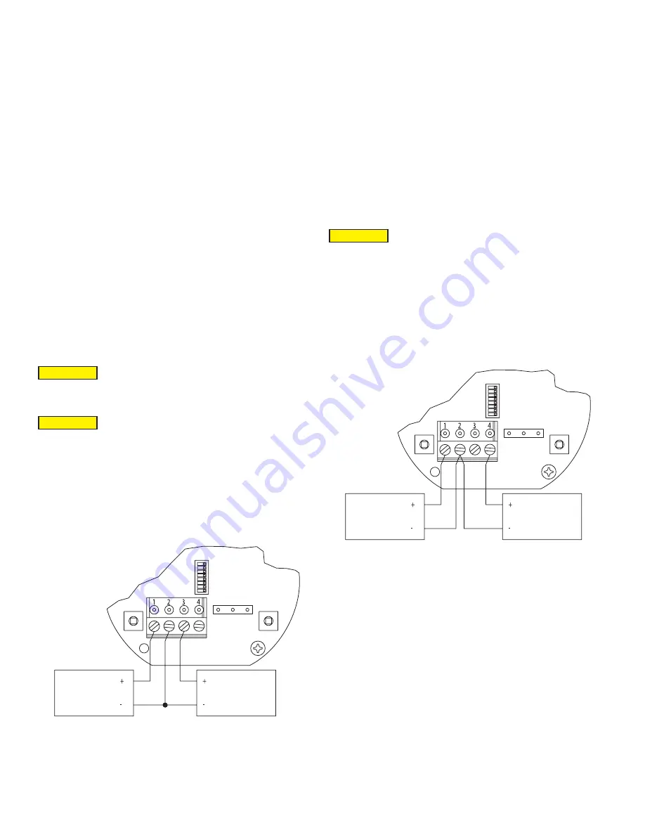
Current Output Operation
The terminal block is removable, and each of the terminals are labeled underneath
the terminal block on the circuit board. As the power supply and outputs share the
same common signal (GND), the outputs may have separate wires but must effectively
join at terminal 2 of the transmitter, as shown in Figure 1. The connections to the
transmitter are made to terminals 1, 2, and 3 (PWR, GND, and IOUT respectively) on
the terminal block as shown in Figure 4.
Figure 1: Current output wiring
Although low loop resistances are recommended, the absolute maximum current loop
load resistance, R
MAX
, is defined by the following the equation:
R
MAX
= (V
PS
– 2.0) / 0.02 where V
PS
is the power supply voltage
For a 24 VDC nominal power supply, this evaluates to R
MAX
= 1100 ohms.
Shielded two wire cable is recommended for current output loop wiring. Ground the
shield at the power supply end only.
The maximum length of connecting wire between the current transmitter and the
receiver is a function of wire size and receiver resistance. That portion of the total
current loop resistance represented by the resistance of the connecting wires
themselves should not exceed 10% of the receiver resistance. For extremely long
runs (over 1,000 ft.), it is desirable to select receivers with higher resistances in order
to keep the size and cost of the connecting leads as low as possible. In installations
where the connecting run is no more than 100 ft, connecting lead wire as small as No.
22 Ga. can be used.
Voltage Output Operation
The terminal block is removable, and each of the terminals are labeled underneath the
terminal block on the circuit board. The voltage output and the power supply must have
separate wire leads that are only joined at terminal 2 of the transmitter, as shown in
Figure 2. Additional error may occur for the voltage output if a single wire is used or if
the wires are joined at the power supply or receiver. The connections to the transmitter
are made to terminals 1, 2, and 4 (PWR, GND, and VOUT respectively) on the terminal
block as shown in Figure 4.
The minimum receiver load is 1 kΩ. The resistance due to the wire should be low
compared to the receiver load resistance. While the voltage at the terminal block
remains unchanged with a 10 mA current flow, resistive losses in the wiring do cause
errors in the voltage delivered to the receiver. For a 1% accurate gauge, the resistance
of the wires should be less than 0.1% of the value of the receiver load resistance. This
will keep the error caused by the current flow below 0.1%.
The output across VOUT and COM will be either 0-5 VDC, 0-10 VDC, or the inverse
depending on the DIP switch setting. See the Analog DIP Switch Settings section for
more information.
Figure 2: Voltage output wiring
SW1
POWER
CURRENT
RECEIVER
SPAN
ZERO
PWR
GN
D
IOUT
VOUT
D1(+
)
D0(-)
CO
M
SW1
POWER
VOLTAGE
RECEIVER
SPAN
ZERO
PWR
GN
D
IOUT
VOUT
D1(+
)
D0(-)
CO
M
DO NOT EXCEED SPECIFIED SUPPLY VOLTAGE RATINGS.
PERMANENT DAMAGE NOT COVERED BY WARRANTY WILL
RESULT.
DO NOT EXCEED SPECIFIED SUPPLY VOLTAGE RATINGS.
PERMANENT DAMAGE NOT COVERED BY WARRANTY WILL
RESULT.
CAUTION
CAUTION
DO NOT EXCEED SPECIFIED SUPPLY VOLTAGE RATINGS.
PERMANENT DAMAGE NOT COVERED BY WARRANTY WILL
RESULT.
CAUTION


