


14
English
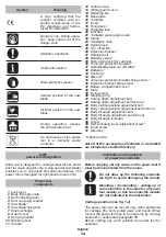
Symbol
Meaning
A sign certifying that the
product complies with es-
sential requirements of the
EU directives and harmo
-
nized EU standards.
Danger zone. During opera-
tion, keep hands out of the
danger zone.
Attention. Important.
Useful information.
Wear protective gloves.
Vertical position of the saw
blade.
Inclined position of the saw
blade.
During operation, remove
the accumulated dust.
Do not dispose of the power
tool in a domestic waste
container.
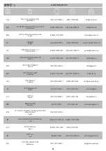
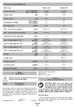
DWT
power tool designation
Mitre saw is designed for cutting timber blanks and is
best for clean angular cuts. Using special saw blades
enables you to cut plastic and aluminum blanks. The
power tool is designed for right-handed users only.
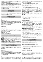
1
Power tool
components
Lock lever
2
Body tilt angle scale
3
Kerf indicating laser *
4
Dust removing coupler
5
Saw blade *
6
Saw blade fixing bolt
7
External flange
8
Guard cover
9
Carrying handle
10
Blocking lever
11
Handle
12
Cramp screw
13
Sliding guard cover
14
Retaining bar
15
Base plate
16
Turntable
17
Insert
18
Fixing lever
19
Turntable lock
20
Indicator
21
Turntable swivel angle scale
22
Clamp *
23
Ventilation slots
24
Spindle lock
25
On / off switch
26
Extension bracket *
27
Retainer bolt
28
Butterfly screw *
29
Body angle lock (for carrying)
30
Turn-over protection bracket *
31
Kerf indicating laser on / off switch *
32
Batteries *
33
Dust bag *
34
Wrench *
35
Turn-over protection bracket fixing screw *
36
Extension bracket fixing screw
37
Battery compartment cover *
38
Plate
39
Fixing screw
40
Mounting ring
41
Cutting depth adjustment bolt
42
Cutting depth adjustment bolt lock-nut
43
Body vertical position adjustment bolt
44
Body vertical position adjustment bolt lock-nut
45
Body tilt angle adjustment bolt
46
Body tilt angle adjustment bolt lock-nut
47
Body tilt angle indicator
48
Screw
49
Kerf indicating laser adjustment screw *
50
Insert screw
51
Allen key *
* Optional extra
Not all of the accessories illustrated or described
are included as standard delivery.
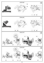
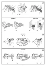
Installation and regulation
of power tool elements
Before carrying out any works on the power tool it
must be disconnected from the mains.
Do not draw up the fastening elements
too tight to avoid damaging the thread.
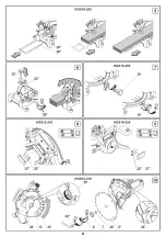
Mounting / dismounting / setting-up of
some elements is the same for all power
tool models, in this case specific models
are not indicated in the illustration.
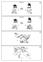
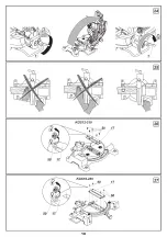
Carriage position (see fig. 1-2)
The power tool can be moved only when positioned
for carriage (the body pulled down and fixed). When
moved, the power tool has to be held only by carrying
handle
9
, or underneath baseplate
15
.
Before starting any work, position the power tool for
operation.
Summary of Contents for KGS12-210
Page 1: ......
Page 4: ...4 ...
Page 5: ...5 ...
Page 6: ...6 ...
Page 7: ...7 ...
Page 8: ...8 ...
Page 9: ...9 ...
Page 10: ...10 ...
Page 48: ...48 ...
Page 49: ...49 ...
Page 50: ...50 ...
Page 51: ...51 ...
Page 52: ...52 ...
Page 53: ...53 ...
Page 54: ...54 ...
Page 55: ...55 ...
Page 56: ...56 ...
Page 57: ...57 ...
Page 73: ...73 ...
Page 74: ...74 ...
Page 75: ......
Page 76: ...76 ...
Page 77: ...77 ...
Page 78: ...78 ...
Page 79: ...79 ...
Page 80: ......


