background image

Physical Installation 

 
1.


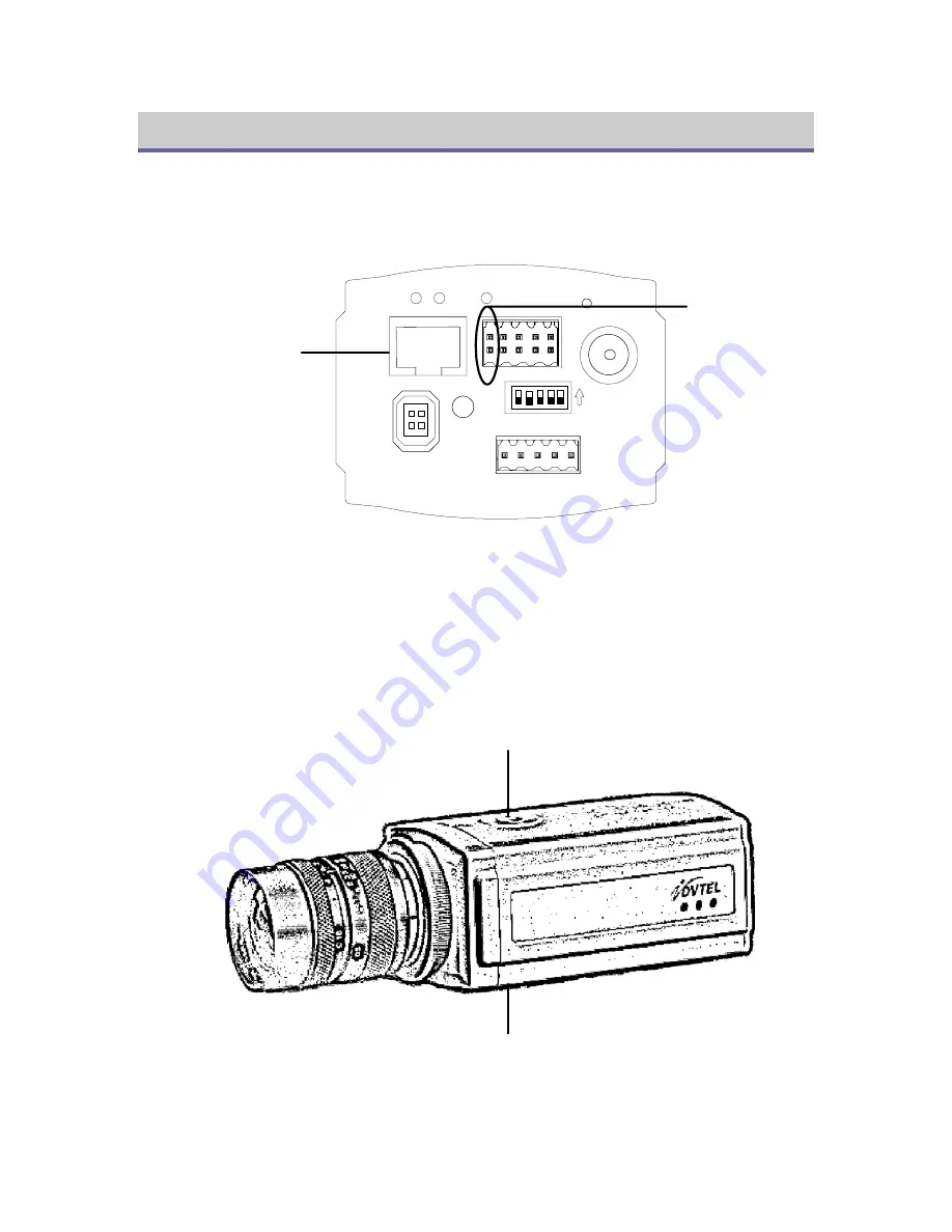
Mount a lens onto the camera. The camera supports fixed, manual and auto iris lenses. If 
applicable, connect the lens to the 

DC LENS

 connector on the back of the camera. The 

camera is factory set for CS-mount lenses, but you can attach a C-mount lens as well. 
 

LINK

ETHERNET

DC LENS

ACT

Rx+Tx+Rx-Tx-GND

RS232 / 485

LEVEL

ON

OFF 1.FLON

2.BLC

3.ALC/ELC

4.AGC

5.Hi-GAIN

STATUS

R

GND

IN2

-

+ R IN1 Lo Li

VIDEO

RESET


12-24 VDC

Power

Connection

Network and

Optional PoE

Connection


Figure 6 - IP Camera Rear Panel 

2.


Using a small screwdriver, connect the power supply’s positive and negative leads to the 
corresponding pins of the 10-block terminal block. Plug the terminal block into the back 
of the camera. You can also power the camera using 

non-standard

 12-24 VDC Power over 

Ethernet. Do not use standard 48 VDC PoE (IEEE 802.3af).  

3.


The camera can be mounted from above or below, using one of its two mounting points. 
Make sure that the brackets and screws you use are able to support the camera and lens’s 
weight. Use standard photographic mounting bolts (1/4 inch UNC-20). 


1/4" Mounting Point

1/4" Mounting Point


Figure 7 - The Camera's Mounting Points 


8

Summary of Contents for 9501-M4-N/P

Page 1: ...DVTel IP Camera Installation Manual M9531A June 05...

Page 2: ...ulations 7 Do not attempt to fix or replace any parts of the camera Refer all servicing to qualified personnel such as DVTel certified dealers and DVTel Technical Support Staff 8 Use only UL Listed Cl...

Page 3: ...Table of Contents PREFACE 4 ENCODER CONFIGURATION 5 ASSIGNING THE CAMERA AN RCP EXTENSION 6 ASSIGNING AN RCP EXTENSION TO A LATITUDE ARCHIVER 7 PHYSICAL INSTALLATION 8 LATITUDE CONFIGURATION 10 3...

Page 4: ...ms The latter option is used to support viewing and recording at different qualities up to 4CIF 30 ips in NTSC or 25 ips in PAL The camera uses 12 24 VDC power and can be configured through its DIP sw...

Page 5: ...d install the latest version of the Java Virtual Machine 4 Using a small screwdriver connect a 12 24 VDC power supply s positive and negative leads to the corresponding pins of the 10 block terminal b...

Page 6: ...ss and a subnet mask such that it is visible to the Latitude system Once you have modified the unit s settings click the Set button and then the link labeled Reboot after set necessary Figure 4 Encode...

Page 7: ...camera with Latitude you will need to associate its RCP port with one or more in the case of fail over or redundant archiving of your Latitude Archivers 1 On the server on which the Latitude Archiver...

Page 8: ...Connection Figure 6 IP Camera Rear Panel 2 Using a small screwdriver connect the power supply s positive and negative leads to the corresponding pins of the 10 block terminal block Plug the terminal...

Page 9: ...an analog monitor to the camera s BNC port 5 If necessary change the DIP switches for Flicker On FLON Back Light Compensation BLC Automatic Light Control Electronic Light Control ALC ELC Automatic Gai...

Page 10: ...fter additional entities have been configured Click Apply changes 5 Click the second tab Recording quality Choose whether default recording quality should be based on the active recording schedule or...

Page 11: ...step after you create additional coverages 9 Click the second to last tab from the left Attributes Make sure Analog format is set to the correct option for your camera PAL or NTSC Click the Live vide...

Reviews: