background image

2-7

Overview

2

1

3

4

5

I

A

2.1.6 Operation Items

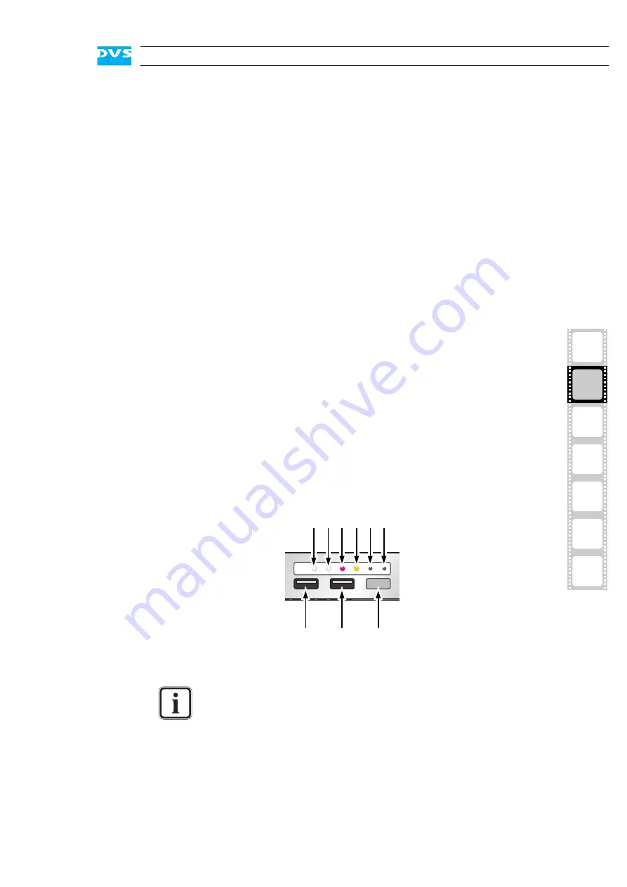
With the operation items at the system’s front the hardware of the 
Cine4K can be controlled (e.g. turned on or off). There you can also find 
LEDs that allow you to assess the state of the system as well as USB 
connectors.

Figure 2-9: Operation items overview

disk carrier

The disk carriers hold each one hard disk of the 
array. The hard disks are mounted to the disk 
carriers with several screws normally located at 
the sides of the carriers.

lever

Once the lever is unlocked with the opener, it 
can be used to pull the disk carrier and its hard 
disk out of the system.

opener

Unlocks the lever and with it the disk carrier.

LED disk power

Shows whether the disk of the disk carrier re-
ceives power.

LED disk activity

Indicates the status of the hard disk of the disk 
carrier (see also section “HDD LEDs” on 
page 2-4):
off

Hard disk is idle.

green

Hard disk is accessed.

red

A hard disk or hard disk carrier related 
error has occurred.

The LEDs can be seen only when they are flashing because 
they are located behind the white strip and thus not visible 
when off.

Further information about what to do in case of an alarm can 
be found in section “Troubleshooting” on page A-2.

1

3

2

4 5 6

7

8

9

Summary of Contents for Cine4K

Page 1: ...Cine4K Hardware Guide Version 1 0 High Resolution Player Cine4K Hardware Guide...

Page 2: ......

Page 3: ...2 1 3 I A 4 5 Cine4K Hardware Guide Introduction Overview Installation Operation Maintenance Appendix Index...

Page 4: ...o event shall DVS Digital Video Systems AG be liable for any dam ages whatsoever including without limitation any special indirect or consequential damages and damages resulting from loss of use data...

Page 5: ...49 511 630070 E mail info dvs de Internet http www dvs de Phone 49 511 67807 25 Fax 49 511 67807 31 E mail support dvs de U S Headquarters DVS Digital Video Inc 300 East Magnolia Boulevard Suite 102 B...

Page 6: ......

Page 7: ...l in this registration form and send or fax it to the address on the right You may also use our online registration form which can be accessed from the following internet page http www dvs de support...

Page 8: ......

Page 9: ...2 1 1 The Front of the System 2 2 2 1 2 DVD Drive 2 3 2 1 3 HDD LEDs 2 4 2 1 4 Faceplate 2 4 2 1 5 Hard Disk Array 2 6 2 1 6 Operation Items 2 7 2 2 Overview of the Rear 2 9 2 2 1 The Rear of the Sys...

Page 10: ...3 Fan Maintenance 5 9 5 4 Power Supply Maintenance 5 12 5 5 Removal of the Faceplate 5 14 A Appendix A 1 A 1 Troubleshooting A 2 A 2 Technical Data A 4 A 2 1 General Technical Data A 4 A 2 2 Dimension...

Page 11: ...er high resolution rasters it supports 4096 2160 in RGB 10 bit at 24 Hz i e the format specified by the DCI who consider 2K as an interim format Furthermore with the Cine4K you can set up top quality...

Page 12: ...rovides safety instructions that you must ad here to and some important notes that you should observe Chapter 2 This chapter gives a front and rear overview of the system detailing all items connector...

Page 13: ...owing typographical conventions will be used in this documen tation y Texts preceded by this symbol describe activities that you must per form in the order indicated Texts preceded by this symbol are...

Page 14: ...ernal components of the Cine4K when ever possible Computer hardware contains components that are sensitive to changing voltages Connecting or disconnecting the Cine4K to or from peripheral hardware wh...

Page 15: ...the warranty period you have to keep the original packing and use it in case of transportation Environmental Conditions For error free working and a long service life the Cine4K needs some basic envi...

Page 16: ...product in it in case of a product return If the customer is not satisfied with the repair DVS will have the option to either attempt a further repair ex change the product or refund the purchase pri...

Page 17: ...results would be Your DVS system has been tested thoroughly and is very reli able However because of the vast amount of third party software available its reactions on the installation of such could...

Page 18: ...1 8 Cine4K Hardware Guide...

Page 19: ...2 1 2 1 3 4 5 2 I A Overview This chapter provides a detailed overview of the Cine4K hardware The system will be shown in a front and a rear view and all its parts and con nectors will be described...

Page 20: ...ection provides an overview of the front of the system Figure 2 1 Overview of the front DVD drive The DVD drive can be used for example for soft ware installations Further information about the DVD dr...

Page 21: ...in more detail in section Hard Disk Array on page 2 6 operation items With the operation items the system can be con trolled e g turned on or off Additionally they of fer some LEDs that allow you to a...

Page 22: ...when off Figure 2 3 HDD LEDs Each LED represents a hard disk of the array Figure 2 4 HDD LEDs and the hard disk array Starting from the left the first six LEDs display the accesses to hard disks in th...

Page 23: ...The top side of the faceplate is hinge fastened while its bottom side is fixed with magnets If you need access to one of the hard disks for ex ample to replace it you just have to lift the faceplate...

Page 24: ...to the system with the help of a disk carrier which makes the removal of a hard disk from the system easy for example in the event of a failure Figure 2 8 Hard disk carrier overview The system hard d...

Page 25: ...nlocked with the opener it can be used to pull the disk carrier and its hard disk out of the system opener Unlocks the lever and with it the disk carrier LED disk power Shows whether the disk of the d...

Page 26: ...ed mute Use a thin pointed object to press this button Some alarms e g the one in case of a hard disk failure are independent of the system alarm and cannot be switched mute with the mute button 6 res...

Page 27: ...2 1 The Rear of the System This section provides an overview of the rear of the system Figure 2 10 Overview of the rear RS 422 This area provides an RS 422 connector Fur ther information about it can...

Page 28: ...onnector slot panel connectors The slot panel connectors of the Cine4K pro vide for example the digital audio and video connections Furthermore if applicable some additional panels may be present for...

Page 29: ...e Cine4K holds the connec tors of the computer system It provides the following connections RS 422 In Out DB 15 HD connector female serial RS 422 interface for master slave control a breakout cable to...

Page 30: ...connector to connect a mouse to your system 2 USB ports These USB connectors universal serial bus offer you the possibility to connect other de vices to your system 3 parallel port DB 25 connector fo...

Page 31: ...evices or a half 19 audio breakout box which is optionally available The latter will then provide the necessary connections in one place please contact DVS for details A pin out of the DB 25 connector...

Page 32: ...section Signal In and Outputs on page A 9 Item Explanation Analog Audio 3 5 mm unbalanced stereo headphone jack to monitor the audio output Digital Audio AES EBU DB 25 connector female for audio signa...

Page 33: ...A B either two indepen dent single link or one dual link connection it can be connected to a breakout cable to provide two standard DVI connectors DVI C D DMS 59 connector for an output of analog and...

Page 34: ...ll the unit out of the power supply once it is unlocked with the latch LED The LED indicates the state of the power supply unit green The power supply unit is operating normally red off The power supp...

Page 35: ...east 1024 768 pixels default manufacturing setting y Connect any other peripheral computer and video equipment For an overview of the panels and connectors at the system s rear see section Overview of...

Page 36: ...3 2 Cine4K Hardware Guide...

Page 37: ...may start the Cine4K at any time To start the system perform the following y Press the power switch briefly to turn on the system The system will be started and the DVS logo in the middle of the face...

Page 38: ...you can initiate a fast shut down by pressing the power switch briefly Some settings will be saved and afterwards the system turns off With the operating system not completely loaded If the operating...

Page 39: ...that you can perform on your own For each work a detailed procedure description is given If you experience trouble with the system that cannot be resolved with the work described here or the section T...

Page 40: ...ks together into a stripe set or RAID The IT world has defined several levels of RAID most of them providing some kind of data protection However to achieve the best possible performance the Cine4K pr...

Page 41: ...erform the following y If appropriate stop all accesses to the hard disk array of your sys tem for example by exiting the video system software and sever ing the network connections y Lift the facepla...

Page 42: ...he disk carrier y Exchange the broken disk with a new one and assemble it in the disk carrier with the screws After that the hard disk is replaced and the disk carrier with the new disk has to be reas...

Page 43: ...fter several minutes the system initializes the new hard disk However to use the disk you have to set up the stripe set of the hard disk array again as well as format it Further infor mation about thi...

Page 44: ...see also section Introduction to RAID on page 5 2 If this is not the case perform a system rescan or reboot the system y Configure the disk sets shown as hard disks as Dynamic Disks y After that sele...

Page 45: ...as the volume label the name Cine4K Storage XXXX with XXXX standing for the capacity of the main storage in gigabyte to the stripe set y Next start the formatting Once the formatting process is finis...

Page 46: ...of the system 2 Figure 5 3 Removal of the cover of the casing Once the cover is slid backward it can be taken off the system 5 2 2 Closing the Casing After finishing your task at hand you have to clo...

Page 47: ...y Open the casing of the system as described in section Opening the Casing on page 5 8 An alarm can be caused by a number of reasons Please refer to section Troubleshooting on page A 2 first for furt...

Page 48: ...ified you can replace it For this perform the following y Press the latch of the respective fan module towards the front of the system 1 y With the locking mechanism released pull the fan module up an...

Page 49: ...fan y Re insert the repaired fan module into the system y Next close the casing of the system as described in section Closing the Casing on page 5 8 With the last step finished you have successfully...

Page 50: ...ply unit y Unscrew the security screw of the latch y Take the handle of the respective unit and press the unit s latch to the left to unlock it y Then pull the unit at its handle out of the power supp...

Page 51: ...y unit y After that check the LED indicating the status of the power supply unit If it is lit up in green the unit is working properly With this the power supply unit has been replaced successfully On...

Page 52: ...le with a jack connection that supplies the DVS logo of the faceplate with power y Unplug the jack connection y Next hold tight the faceplate and remove the hinge wires as indi cated in the following...

Page 53: ...ives some hints how to resolve irregularities during operation After that technical data and general information about the Cine4K are provided This chapter also provides information about how to confi...

Page 54: ...tect the worn disk s replace them as de scribed in section Hard Disk Main tenance on page 5 2 Otherwise contact the DVS service department An alarm is sounded and the alarm LED is lit The alarm can be...

Page 55: ...nded and the alarm LED is off The alarm cannot be switched mute with the mute but ton OR At start up the sys tem is not able to ini tialize a disk set i e one or more hard disks are not recog nized by...

Page 56: ...r is conducted to the rear of the rack and properly vented away Weight approx 70 kg Environment also during transport No exposure to heat No exposure to strong electric or magnetic fields No vibration...

Page 57: ...ude from the rear plug safety l minus j usually plus 150 mm However this amount of space depends on the type of connectors used Figure A 1 Measured dimensions a 220 mm g 197 mm b 199 mm h 50 mm c 21 m...

Page 58: ...Adjust the jumpers on the printed board and set them to the required configuration Figure A 2 Jumper settings for audio circuit board The system your are working on operates with voltages that can be...

Page 59: ...cifications Video Input Output DVI analog and digital 2 DMS 59 4 DVI I via break out cables Audio Input Output AES EBU 4 Digital Stereo Channels 1 DB 25 XLR via breakout cable Analog Audio 1 stereo he...

Page 60: ...50 59 94 60 71 928 72 750 1280 720 16 9 1035i 29 97 30 1125 1920 1035 16 9 1080i 23 976 24 25 29 97 30 1125 1920 1080 16 9 1080p 23 976 24 25 29 97 30 47 952 48 50 59 94 60 1125 1920 1080 16 9 1080ps...

Page 61: ...I1_TX2 45 DVI2_TX CLK 6 VGA1_SCL 26 DVI1_TX2 46 GND 7 VGA1_SDA 27 DVI1_TX1 47 VGA2_GREEN 8 GND 28 DVI1_TX1 48 9 VGA2_SDA 29 DVI1_TX0 49 DVI2_CLK GND 10 VGA2_SCL 30 DVI1_TX0 50 VGA2_HSYNC 11 5V 31 DVI1...

Page 62: ...18 TX_0 3 GND 11 DVI_CLK_B 19 DVI_CLK_B 4 TX_4 12 TX_3 20 TX_5 5 TX_4 13 TX_3 21 TX_5 6 DDC_CLK 14 5V 22 GND 7 DDC_DAT 15 GND 23 TX_CLK 8 ANALOG_VSYNC 16 HP_DETECT 24 TX_CLK C1 ANALOG_RED C3 ANALOG_BL...

Page 63: ...UT CH 7 8 or LTC OUT 2 GND 15 Audio OUT CH 5 6 3 Audio OUT CH 5 6 16 GND 4 Audio OUT CH 3 4 17 Audio OUT CH 3 4 5 GND 18 Audio OUT CH 1 2 6 Audio OUT CH 1 2 19 GND 7 Audio IN CH 7 8 or LTC IN 20 Audio...

Page 64: ...5 Pin D Sub HD Connector Pin No Signal Pin No Signal 1 RX_A_CON 9 GND 2 10 TX_B_CON 3 TX_A_CON 11 GND 4 RX_B_CON 12 RX_A_CON 5 GND 13 TX_B_CON 6 TX_A_CON 14 7 GND 15 RX_B_CON 8 external view female on...

Page 65: ...t cable that will then provide two female DB 9 connec tors for a standard RS 422 connection see section RS 422 on page 2 10 RMT OUT RMT 1 RMT IN RMT 2 Pin No Signal Pin No Signal 1 1 2 RX_A_CON 2 TX_B...

Page 66: ...Otherwise the warranty will be void In any other case if you do not have the original packing any more use a similar structured packing for transportation DVS cannot be held liable for damages due to...

Page 67: ...A 15 2 1 3 4 5 Appendix I A Figure 3 Figure 4 Figure 5 a b c Box A Box B Box B Box B Box B Box B...

Page 68: ...Marking DVS Digital Video Systems AG herewith declares that the following product s according to the provisions of the mentioned EC Directives including their relevant revisions at the time of this d...

Page 69: ...ommunications Op eration of this equipment in a residential area is likely to cause harmful interference in which case the user will be required to correct the inter ference at his own expense Note Co...

Page 70: ...A 18 Cine4K Hardware Guide...

Page 71: ...kout box audio 2 13 breakout cable digital audio 2 13 2 14 DVI 2 14 RS 422 2 10 A 13 casing close 5 8 open 5 8 chapter overview 1 2 Cine4K 1 1 configuring audio LTC A 6 installation 3 1 main storage 2...

Page 72: ...ormat 5 7 hard disk s 2 6 activity 2 2 2 4 2 7 assembly 5 4 disk power LED 2 7 disk set 5 2 failure 5 2 5 3 removal 5 3 replace 5 4 status 2 2 2 4 2 7 hinge 2 5 5 14 important notes 1 6 1 7 installati...

Page 73: ...s 5 2 disk set 5 2 rear overview 2 9 remote control pin outs 9 pin D Sub A 13 15 pin D Sub A 12 removal of the faceplate 5 14 reset button 2 8 RS 232 2 12 RS 422 2 9 2 10 breakout cable 2 10 A 13 S T...

Page 74: ...I 4 Cine4K Hardware Guide...

Reviews: